2 layers57.3 × 19 mm

 gheadcn/Video-Amplifier
A simple video amplifier designed for use in a SuperGun
Video Amplifier is an open-source printed circuit board by gheadcn, from the gheadcn/Video-Amplifier repository on GitHub, published under the MIT licence. It is a 2-layer board of 55.9 × 38.1 mm with 26 parts on 28 nets, routed with 91 tracks and 0 vias.
Its parts include 12 resistors, 8 capacitors, 3 connectors and 1 IC. It belongs with the audio and music boards of this library.
A simple video amplifier designed for use in a SuperGun. The board is a light wrapper around the TI THS7374 Video Amplifier. It takes in an RBSs signal from a JAMMA board (0–3V AC swing, 0–5V DC bias, high input impedance: 1–10kΩ) and converts it to consumer set friendly outputs (RGB inputs: 0.7V AC, 0–2V DC bias, at 75 ohms impedance).

The basic idea behind the board is to be configurable to how you want it. The input and outputs are designed as terminal blocks that can take any 20 - 26 AWG wire which makes it easy to connect to just about anything on both sides. In cases where you might be more certain on how you're going to install it, the terminal blocks can easily be omitted and wires soldered directly to the board. Wiring into any standard connector is similarly easy if for instance you wanted to wire in a VGA connector.
This is part of a broader collection of projects to piece by piece build up the components of a supergun.
This board has been fabbed via Oshpark, fully assembled, and tested as working.

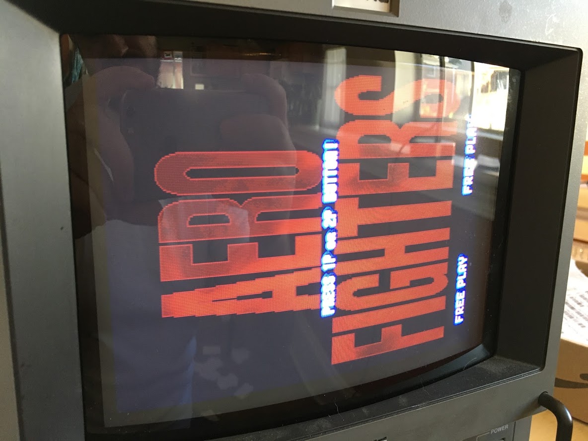
In future revisions I would like to decouple the power ground from the video ground to increase the potential applications of the board. This seems like a completely reasonable design in the scope of a board focused on JAMMA compatibility where almost always video ground and power ground are coupled. But I realized this flaw when I wanted to power my board via an external source and realized the design wouldn't work.
The project root contains a .pcb and a .bom file. The pcb files defines the board geometry and traces. Popular fabricator Oshpark offers the ability to submit the .pcb file directly to them for manufacturing. To have three boards produced should cost about $16 as of writing this. If people have experience with submitting KiCad projects to other manufacturers (I tested producing gerber outputs with pcbnew and it seemed fine) I would be happy to expand these instructions.
The BOM file or "Bill of Materials" lists a suggested set of parts and links to buy those parts on mouser.com (correct at time of publishing). You expect the cost per board of materials to run you about $7.
If you don't have them already you will also need a JAMMA harness and an arcade power supply. Both of these can be easily purchased online, or in the case of the JAMMA harness assembled. I've provided links to examples below (I don't vouch for these products but want to give folks an easy way to understand what kinds of products are required).
Note: The boards will come rough, take the time to grab a little sand paper and smooth the edges before beginning.
The approach we'll take to assembly will try to minimize the amount of time and work required before we can test the work. With some minor deviations, we will start at the top right and work our way left to right and then top to bottom.
Might as well get the hard part out of the way first and this is it. Besides you'll want room to do this and don't want anything in your way. It's unfortunate that the THS7374 is only sold in surface mount packages and hand soldering surface mount components is a pain. I recommend a pair of fine tweezers, lots of flux, and the "drag" method. This video from eevblog demonstrates the method starting around the 5 minute mark.
I've set up the board to be built with terminal blocks for signal inputs and outputs and a 2 pin JST connector as 5v power. On the left is a 4 pin terminal block for the 4 input signals (Red, Green, Blue, and Sync) and the 2 pin JST power connector. On the right is a 5 pin terminal block connector for the outputs and ground (Red, Green, Blue, Sync, and Ground).
One little caveat is that at least with the harness that I purchased there isn't an easy way to tap 5v off the supply. In my case I removed a little bit of heat shrink tubing that was protecting the 5v pins on the JAMMA connector and soldered a little line off of that for power.
Technically you could order your signals any way you like, but I always stick with Red, Green, Blue, Sync. In this step we'll put in the top two signal lines Red and Green. Each line consists of a 1K Ohm resistor, a 390 Ohm resistor, a small 0.1uf coupling capacitor, a 75 Ohm resistor, and a 330uf electrolytic capacitor (Note: these are polarized please pat attention to the markings on the board). When both the Red and Green lines are assembled we can move onto our first test.
In order to run a good test we need both a color signal and sync (read more on component video), without the sync signal you'll end up with a garbled picture. While in the last step we assembled the Red and Green signal lines, the reality is that every signal is handled exactly the same, so we can just attach the sync signal to green to get a test going.
If everything is set up right you should get the image from your board but only in Red.
If the test went well, procede copying Step 2 for the remaining signals Blue, and Sync. Test along the way as you feel comfortable
Honestly, I have no experience managing KiCad projects in an opensource community. I can tell from my edits that there can be a large blast radius in a diff from a small observable change. This is something we'll have to work through together. If you have changes you'd like to see, make a PR and we'll work through it together.
| Qty | Value | Footprint | References |
|---|---|---|---|
| 4 | 0.1uf | SamacSys:K104M15X7RF53L2 | C1, C2, C3, C4 |
| 4 | 1k | Resistor_THT:R_Axial_DIN0204_L3.6mm_D1.6mm_P5.08mm_Horizontal | R1, R2, R3, R4 |
| 4 | 330uf | Capacitor_THT:CP_Radial_D6.3mm_P2.50mm | C5, C6, C7, C8 |
| 4 | 390 | Resistor_THT:R_Axial_DIN0204_L3.6mm_D1.6mm_P5.08mm_Horizontal | R5, R6, R7, R8 |
| 4 | 75 | Resistor_THT:R_Axial_DIN0204_L3.6mm_D1.6mm_P5.08mm_Horizontal | R9, R10, R11, R12 |
| 1 | Power In | Connector_JST:JST_XH_B2B-XH-AM_1x02_P2.50mm_Vertical | J2 |
| 1 | Signal In | SamacSys:TB00150004BE | J1 |
| 1 | Signal Out | SamacSys:TB003500P05BE | J3 |
| 1 | THS7374IPWR | SamacSys:SOP65P640X120-14N | IC1 |
The 24 most common of 26 parts.
It measures 55.9 × 38.1 mm and has 2 copper layers, 1.6 mm thick.
26 parts. The full list of its parts is on this page, with links to each part's symbol and footprint where PCBKit's library has them.
From the gheadcn/Video-Amplifier repository on GitHub, at the commit this page was made from: the board is VideoAmplifier.kicad_pcb. PCBKit opens the board in the browser, with nothing to install.
Its repository publishes it under the MIT licence: you may reuse it on that licence's terms (keep the author's notice, and for a copyleft licence share your changes alike).

hackclub/OnBoard
💡 Join 1,000 teenagers and make your first PCB with a $100 grant!


harbaum/galagino
A Galaga, Pac-Man and Donkey Kong arcade emulator for the ESP32

Luos-io/luos_engine
Open-source and real-time orchestrator for cyber-physical-systems, to easily design, test and deploy embedded applications and digital twins.

google/walt
A device for measuring latency of physical sensors and outputs on phones and computers
