4 layers337.6 × 105.7 mm
ISA CGA
hkzlab/CGA_Redux
The Color Graphics Adapter Redux board is a more or less faithful clone of the original IBM CGA, based on the original schematics
170 parts56

 gfoot/compvideo650236
Composite/component video output for homebrew 6502 computers
Simplevideo is an open-source printed circuit board by gfoot, from the gfoot/compvideo6502 repository on GitHub, published under the Unlicense licence. It is a 4-layer board of 276.9 × 172.7 mm with 65 parts on 149 nets, routed with 1,801 tracks and 759 vias.
It is built around the 74LS245SC, CD74HC40103E and 74HC74D, with the 74LS74PC, 74LS00SC and 74LS166AP-E among its other parts. Its parts include 31 ICs, 11 capacitors, 11 resistors, 4 diodes and 4 connectors. It belongs with the retro computing and games boards of this library.


 |  |
 |
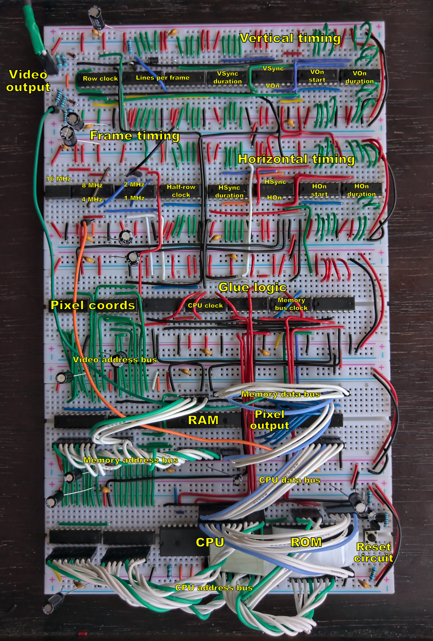
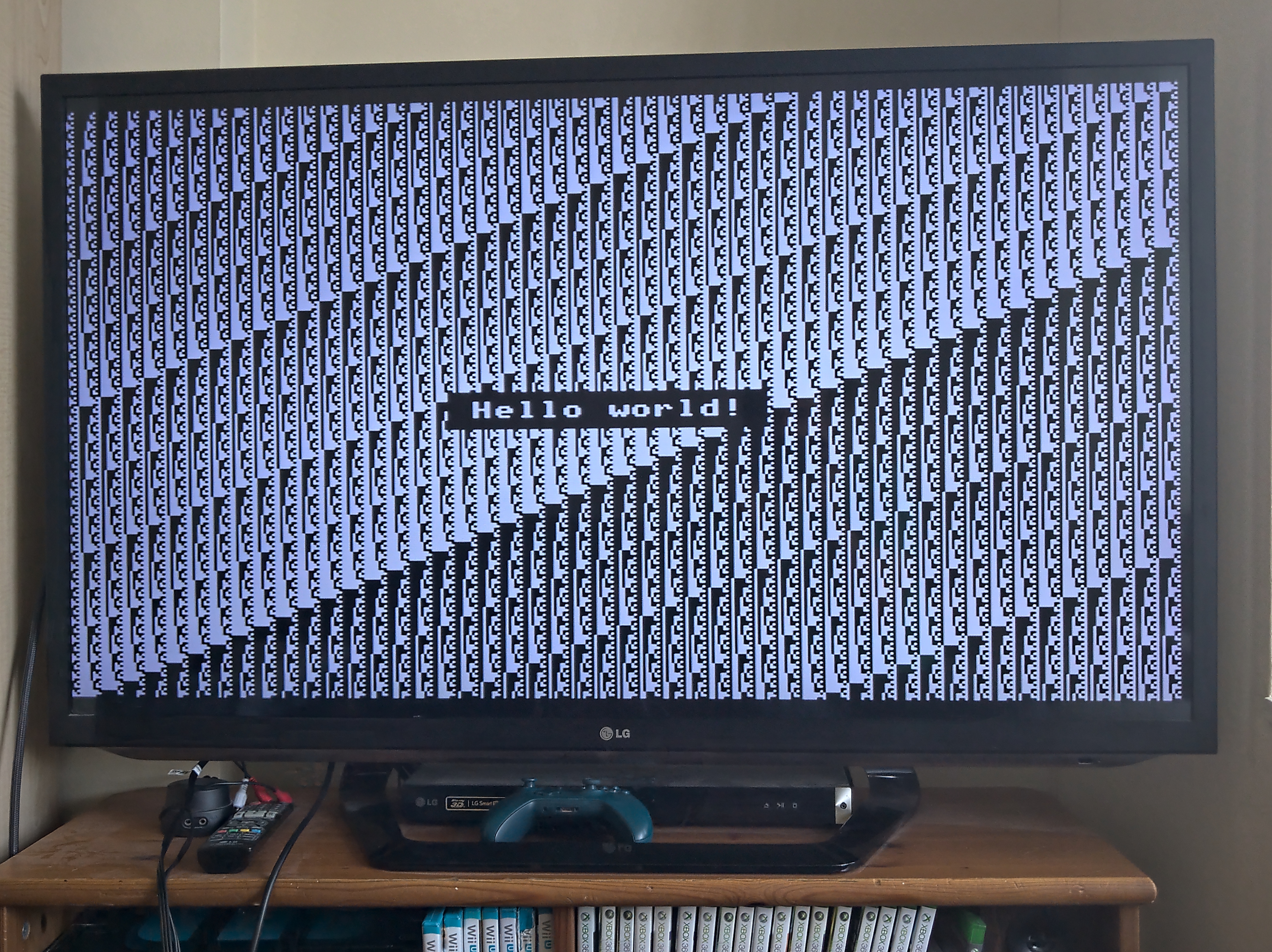
This is my second iteration video output circuit for homebrew 6502 computers. It's designed to work in a way that's fairly close to how early 80s microcomputers tended to work, which means RAM shared between CPU and video controller, as this tends to provide the fastest possible access for the CPU to the video memory.
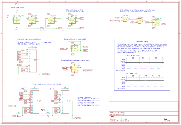
In this second iteration, the main change from V1 is that the timings are easily configurable, allowing it to support NTSC as well as PAL with just a few jumper changes, as well as non-standard sync timings if you want to experiment; and the image placement and size is also easily configurable.
You can also use interlacing to double the vertical resolution to 512 pixels, and if you swap the clock crystal and adjust some other timings, you can double the horizontal resolution as well.
More involved, higher clock frequencies and maybe more counters would also allow HD resolutions such as 720p and 1080i, though I haven't tried those yet, and VGA if you also change the output layer to output plain RGB.
The limiting factor at these higher resolutions becomes memory - 384x256x2 already uses nearly half of the RAM. I'm considering addressing this through a banking scheme in an upcoming V3.
This project contains:
This includes the 6502, RAM, ROM, oscillator, reset circuit, and address decoding circuits, along with the video controller. If you're already happy with the way you're doing those in an existing system then you could mostly keep your old design instead, but the RAM and clock need to be integrated here, in order to be shared with the video controller.
There are a few things I plan to do next, and I'm not sure what the order will be. Feedback/contributions welcome - let me know if you try these or have other ideas!
The output impedance isn't exactly what it's meant to be, but it's close enough I think.
The 16MHz base frequency is what the BBC Micro used back in the day, but I think in the digital age the standard pixel sampling frequency for SDTV is 13.5MHz. As a result, on an LCD display you get blurring and moire effects at 8MHz; and at 16MHz you lose most of the pixel detail completely. I think with a 13.5MHz base frequency the picture would be sharper overall.
My first iteration output correct pre- and post-vsync equalization pulses, and serrations during the vsync; I left that out this time around as it doesn't seem to be necessary these days. Maybe I'm missing something though. As far as I can tell chips like the 6845 never supported this anyway - at least it's not mentioned in the datasheets. So I'm guessing that since at least the 1980s nobody has bothered with them.
I haven't worked out interlacing yet. Websites say that you can turn it off with the right combination of sync pulses, but my TV always says it's interlaced, so either I'm doing it wrong, or the TV just never says "576p" anyway. The design here is intentionally fully-interlaced, which might lead to increased vertical resolution in the end. It should be possible to uninterlace it with a small change to the sync timings. Actually I suspect that this is becase composite doesn't support progressive scan - with component video the non-interlaced mode might work better.
I used a lot of 74HCT40103s in this design - they're incredibly useful, and were fundamental to the simplification and tweakability of the timings in this design. However it seems they might be harder to find online than other chips I tend to use - I had to order a second batch, and it was harder to find them this time around. So maybe it wasn't the best choice... It's possible to use 74HCT163s instead, but you'll need more of them as they're only 4-bit counters.
| Qty | Value | Footprint | References |
|---|---|---|---|
| 10 | 220u | Capacitor_THT:CP_Radial_D5.0mm_P2.50mm | C2, C3, C4, C5, C6, C7, C8, C9, C10, C11 |
| 9 | CD74HC40103 | Package_DIP:DIP-16_W7.62mm | U3, U7, U8, U10, U11, U12, U14, U15, U16 |
| 5 | 74HC74 | Package_DIP:DIP-14_W7.62mm | U6, U9, U20, U30, U31 |
| 5 | 74LS245 | Package_DIP:DIP-20_W7.62mm | U21, U23, U24, U28, U29 |
| 4 | 1N4148 | Diode_THT:D_DO-34_SOD68_P7.62mm_Horizontal | D1, D2, D3, D4 |
| 3 | Conn_01x08 | Connector_PinHeader_2.54mm:PinHeader_1x08_P2.54mm_Vertical | J2, J3, J4 |
| 2 | 100K | Resistor_THT:R_Axial_DIN0207_L6.3mm_D2.5mm_P7.62mm_Horizontal | R5, R11 |
| 2 | 1K | Resistor_THT:R_Axial_DIN0207_L6.3mm_D2.5mm_P7.62mm_Horizontal | R2, R6 |
| 2 | 4040 | Package_DIP:DIP-16_W7.62mm | U4, U5 |
| 2 | 74LS74 | Package_DIP:DIP-14_W7.62mm | U13, U17 |
| 1 | 10K | Resistor_THT:R_Axial_DIN0207_L6.3mm_D2.5mm_P7.62mm_Horizontal | R3 |
| 1 | 1u | Capacitor_THT:CP_Radial_D5.0mm_P2.50mm | C1 |
| 1 | 20 | Resistor_THT:R_Axial_DIN0204_L3.6mm_D1.6mm_P7.62mm_Horizontal | R8 |
| 1 | 200 | Resistor_THT:R_Axial_DIN0204_L3.6mm_D1.6mm_P7.62mm_Horizontal | R7 |
| 1 | 22k | Resistor_THT:R_Axial_DIN0204_L3.6mm_D1.6mm_P7.62mm_Horizontal | R1 |
| 1 | 28C256 | Package_DIP:DIP-28_W15.24mm | U27 |
| 1 | 2K2 | Resistor_THT:R_Axial_DIN0204_L3.6mm_D1.6mm_P7.62mm_Horizontal | R9 |
| 1 | 2N3904 | Package_TO_SOT_THT:TO-92_Inline | Q3 |
| 1 | 2N3906 | Package_TO_SOT_THT:TO-92_Inline | Q1 |
| 1 | 330 | Resistor_THT:R_Axial_DIN0204_L3.6mm_D1.6mm_P7.62mm_Horizontal | R4 |
| 1 | 47 | Resistor_THT:R_Axial_DIN0204_L3.6mm_D1.6mm_P7.62mm_Horizontal | R10 |
| 1 | 62256 | Package_DIP:DIP-28_W15.24mm | U26 |
| 1 | 74LS00 | Package_DIP:DIP-14_W7.62mm | U19 |
| 1 | 74LS08 | Package_DIP:DIP-14_W7.62mm | U2 |
| 1 | 74LS138 | Package_DIP:DIP-16_W7.62mm | U32 |
| 1 | 74LS166 | Package_DIP:DIP-16_W7.62mm | U25 |
| 1 | 74LS32 | Package_DIP:DIP-14_W7.62mm | U22 |
| 1 | CXO_DIP8 | Oscillator:Oscillator_DIP-8 | X1 |
| 1 | Conn_01x02 | Connector_PinHeader_2.54mm:PinHeader_1x02_P2.54mm_Vertical | J1 |
| 1 | SW_Push | Button_Switch_THT:SW_PUSH_6mm | SW1 |
| 1 | WD65C02_ | Package_DIP:DIP-40_W15.24mm | U18 |
It measures 276.9 × 172.7 mm and has 4 copper layers, 1.6 mm thick.
65 parts, built around the 74LS245SC, CD74HC40103E, 74HC74D and 74LS74PC. The full list of its parts is on this page, with links to each part's symbol and footprint where PCBKit's library has them.
From the gfoot/compvideo6502 repository on GitHub, at the commit this page was made from: the board is simplevideo/simplevideo.kicad_pcb. PCBKit opens the board in the browser, with nothing to install.
Its repository publishes it under the Unlicense licence: you may reuse it on that licence's terms (keep the author's notice, and for a copyleft licence share your changes alike).
hkzlab/CGA_Redux
The Color Graphics Adapter Redux board is a more or less faithful clone of the original IBM CGA, based on the original schematics


misterblack1/zenith_zt1
Information gathered on the Zenith ZT-1 / ZT-10 / ZT-11 and ZTX/ZT-x-A variants

RetroStack/TRS-80-Model-I-Jap50-E1
Hardware Replica of the TRS-80 Model I Revision HE11E011550

felipesanches/Itautec_I7000_KICAD
Esquemáticos do computador Itautec I-7000 G desenhados a partir de inspeção do circuito das PCBs

clemarfolly/Microdigital-TK2000
Reprodução da PCB do TK-2000 da Microdigital, clone do Micro-Professor MPF-II
