

2 layers181 × 97 mm
OpenDeck r3.1.2
shanteacontrols/OpenDeck
A platform for building interactive control and sensing devices using MIDI and OSC built with Zephyr RTOS.
262 parts960Apache-2.0

 gergelytothh/metromap
A lit-up Budapest metro map: ESP32, two MAX7219 LED drivers, a custom KiCAD PCB and 96 hand-wired LEDs.
Metromap is an open-source printed circuit board by gergelytothh, from the gergelytothh/metromap repository on GitHub, published under the MIT licence. It is a 2-layer board with 46 parts on 40 nets, routed with 106 tracks and 1 via.
It is built around the MAX7219M. Its parts include 2 capacitors, 2 ICs and 1 resistor. It belongs with the lEDs and displays boards and the ESP32 boards of this library.
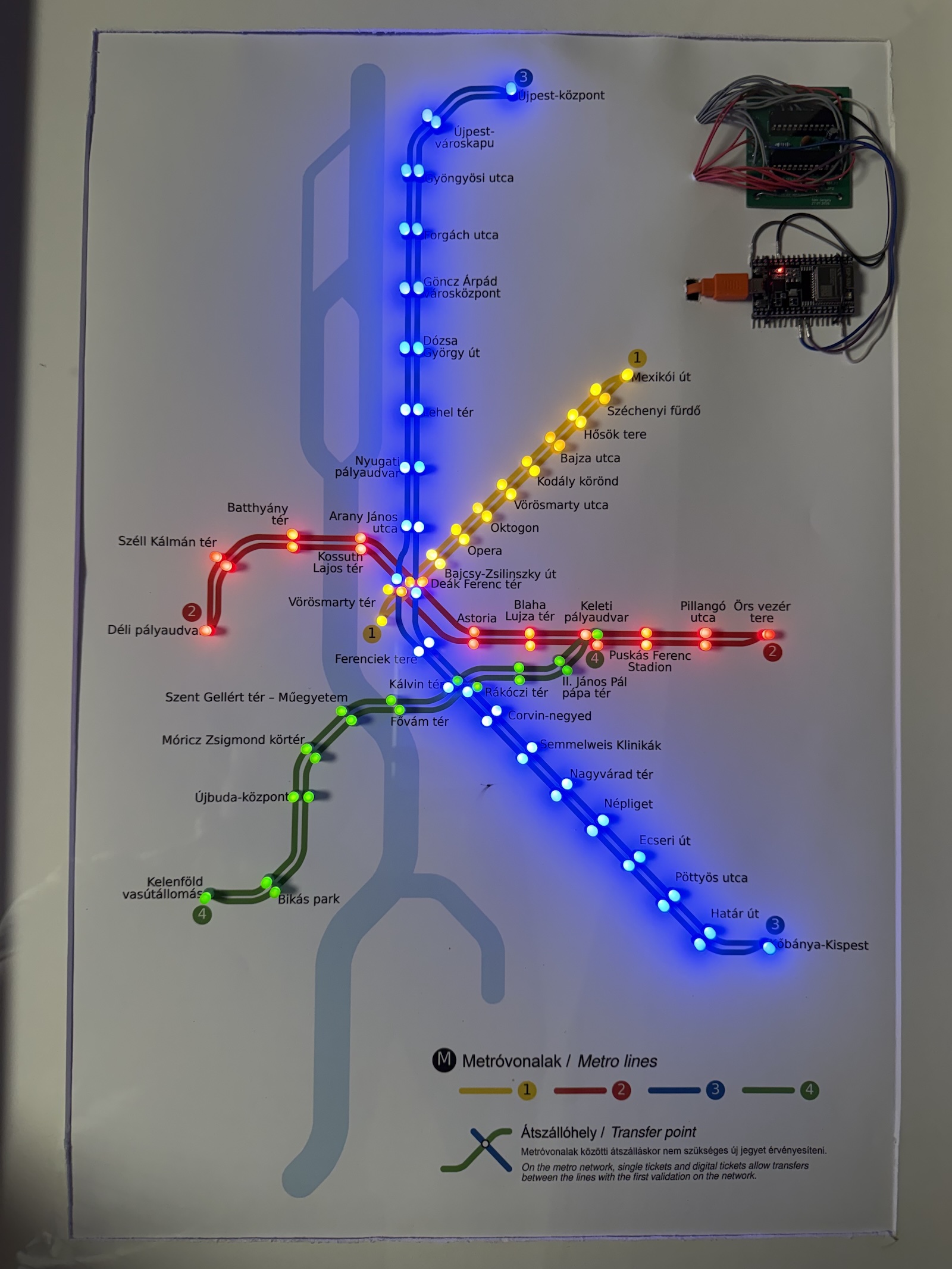
A map of the Budapest metro, designed to show trains moving on all four lines. There are 96 LEDs on the map: two at each station (one per direction) and one at each terminus. They are hand-wired and soldered onto the map and driven by an ESP32 through a custom PCB. Right now it runs a simulated train animation; live data from BKK is the next step.
I'd seen lit-up metro maps of other cities online, but none of Budapest, and I didn't like the design of the ones I found. Since I'm studying electrical engineering anyway, I decided to build my own.
The LEDs are driven by two MAX7219 chips, controlled by an ESP32. Each chip has 16 outputs: 8 DIG (digit) pins that sink current and 8 SEG (segment) pins that source it. Each LED sits where one DIG line and one SEG line cross, so one chip can control 64 LEDs and the two together 128.
Only one DIG line is active at a time. The chip sets the SEG lines for the LEDs that should be lit in that row, pulls the DIG line low, then moves on to the next row. It cycles through all 8 rows hundreds of times a second, so every lit LED looks constantly on.
The two chips are daisy-chained: they share the ESP32's clock and load pins, and U1's data output feeds U2's data input. The ESP32 shifts out 32 bits, a 16-bit word for each chip (an 8-bit register address and 8 bits of data, which set the SEG lines for one DIG row), and then a pulse on LOAD makes both chips apply them at the same time.
There are 96 LEDs, so one chip wasn't enough. I split them by metro line, so each line stays on a single chip and both chips stay under the 64-LED limit:
| Chip | Lines | LEDs used | Spare slots |
|---|---|---|---|
| U1 | M1 + M2 | 40 | 24 |
| U2 | M3 + M4 | 56 | 8 |
Every LED has an ID (1–96) and is assigned a chip, a DIG and a SEG. This mapping table is in station_map.h (also as a CSV).
The firmware builds on this table:
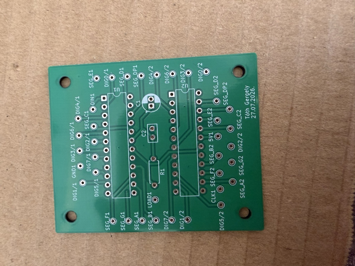
I designed the driver PCB myself in KiCAD and had it made by NYÁKÁRUHÁZ Kft. It holds both MAX7219s in DIP sockets, so the soldering heat couldn't damage the chips. Every DIG and SEG pin goes to a labelled pad.
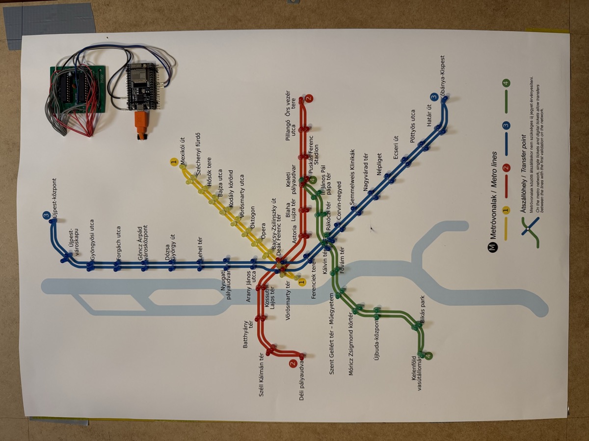
From each pad, a wire runs to the back of the map, where it connects to the right LEDs. That's around ~280 solder joints in total, all by hand.
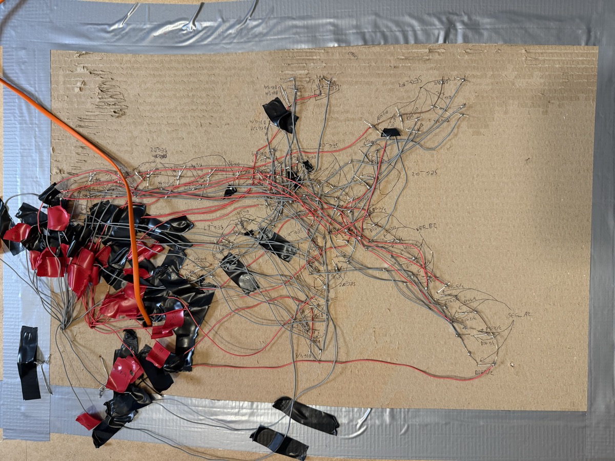 The back of the map. Every wire is labelled in pencil with its DIG/SEG line.
| Part | What |
|---|---|
| Microcontroller | ESP32-WROOM-32U dev board |
| LED drivers | 2 × MAX7219 (DIP-24, socketed) |
| PCB | Own design in KiCAD, made by NYÁKÁRUHÁZ Kft. |
| LEDs | 96, one colour per line |
| Map | Printed poster on cardboard |
| Power | 5 V from USB, via the ESP32 |
Design files: schematic (PDF) · KiCAD project · 3D render
Built with Arduino IDE 2.3.10 and the Espressif ESP32 board package 3.3.12.
firmware/metromap/metromap.ino.Pick the mode in loop(): trainMode() runs the train animation, and walkTest() lights every LED in turn and prints each station to the Serial Monitor (115200 baud).
For a long time the addressing didn't work: telling the firmware to light a specific DIG/SEG lit the wrong LED. I lit one address at a time and wrote down which LED actually came on, until a pattern appeared: the MD_MAX72xx library numbers the columns in a different order from the chip's SEG pins. SEG_A is column 6, down to SEG_G at column 0, and only SEG_DP stays at column 7. I then tested that theory LED by LED, and it held. The fix is a single line in metromap.ino.
More in the bring-up log, including how the datasheet corrected my assumption about the shared ISET resistor.
The firmware and this README were developed in collaboration with Claude and Claude Code. The hardware design, PCB, wiring and testing are my own.
| Qty | Value | Footprint | References |
|---|---|---|---|
| 36 | ~ | TestPoint:TestPoint_THTPad_D1.5mm_Drill0.7mm | 5V1, CLK1, DIG0/1, DIG0/2, DIG1/1, DIG1/2, DIG2/1, DIG2/2, DIG3/1, DIG3/2, DIG4/1, DIG4/2, DIG5/1, DIG5/2, DIG6/1, DIG6/2 +20 |
| 4 | MountingHole | MountingHole:MountingHole_3.2mm_M3 | H1, H2, H3, H4 |
| 2 | MAX7219 | Package_DIP:DIP-24_W7.62mm | U1, U2 |
| 1 | 100nF | Capacitor_THT:C_Disc_D5.0mm_W2.5mm_P2.50mm | C2 |
| 1 | 10k | Resistor_THT:R_Axial_DIN0207_L6.3mm_D2.5mm_P7.62mm_Horizontal | R1 |
| 1 | 10uF | Capacitor_THT:CP_Radial_D5.0mm_P2.00mm | C1 |
| 1 | ~ | TestPoint:TestPoint_THTPad_D1.0mm_Drill0.5mm | SEG_DP1 |
shanteacontrols/OpenDeck
A platform for building interactive control and sensing devices using MIDI and OSC built with Zephyr RTOS.


StarGate01/hl-alyx-glove
Firmware and Hardware for a Half-Life: Alyx Gravity Glove Replica


Eigenbaukombinat/glowboard
The Glowboard Plotter plots images using 64 UV LEDs attached in a line moved over a 120cmx60cm glow-in-the-dark sheet by a stepper.


46 parts, built around the MAX7219M. The full list of its parts is on this page, with links to each part's symbol and footprint where PCBKit's library has them.
From the gergelytothh/metromap repository on GitHub, at the commit this page was made from: the board is hardware/kicad/Metro Map.kicad_pcb and its schematic hardware/kicad/Metro Map.kicad_sch. PCBKit opens the board in the browser, with nothing to install.
Its repository publishes it under the MIT licence: you may reuse it on that licence's terms (keep the author's notice, and for a copyleft licence share your changes alike).