2 layers
Encoder
byrantech/laptop
anyon_e, a highly integrated, high end, open source laptop. Attempt the impossible.
7 parts4.3kMIT

 GavishtK/AeThEriON1
ESP32-Based Attitude Indicator Wireless Flight Instrumentation System
Aether is an open-source printed circuit board by GavishtK, from the GavishtK/AeThEriON repository on GitHub, published under the MIT licence. It is a 2-layer board of 68.5 × 70.5 mm with 7 parts on 46 nets, routed with 61 tracks and 0 vias.
Its parts include 3 resistors, 1 IC, 1 diode and 1 connector. It belongs with the ESP32 boards of this library.
ESP32-Based Attitude Indicator & Wireless Flight Instrumentation System





Real-time flight attitude indicator with a wireless OLED display and a full web-based analytics dashboard.
50 Hz telemetry | 25 FPS OLED | 60 FPS horizon | AI analysis | Flight recording & replay | SQLite-quality sensor diagnostics
AETHERION AI is a self-contained, open-source flight instrumentation system built on the ESP32. It combines:
The ESP32 runs in Access Point mode, creating its own Wi-Fi network so no router is required. The dashboard is stored on-board in LittleFS flash and served over HTTP, while telemetry is streamed over a WebSocket server at 50 Hz.
graph LR
    subgraph "firmware/Aetherion"
        A[Aetherion.ino<br/>Main Entry]
        B[config.h<br/>Configuration]
        C[imu.cpp/h<br/>Sensor Driver<br/>MPU6050 + Madgwick]
        D[graphics.cpp/h<br/>OLED Rendering<br/>U8g2 / PFD]
        E[web.cpp/h<br/>HTTP + WS Server<br/>LittleFS]
        F[rgb.cpp/h<br/>LED Status]
    end

    A --> B
    A --> C
    A --> D
    A --> E
    A --> F
    C -->|IMUData| D
    C -->|IMUData| A
    D -->|drawPFD| A
    E -->|handleWebClient| A
    F -->|Status| A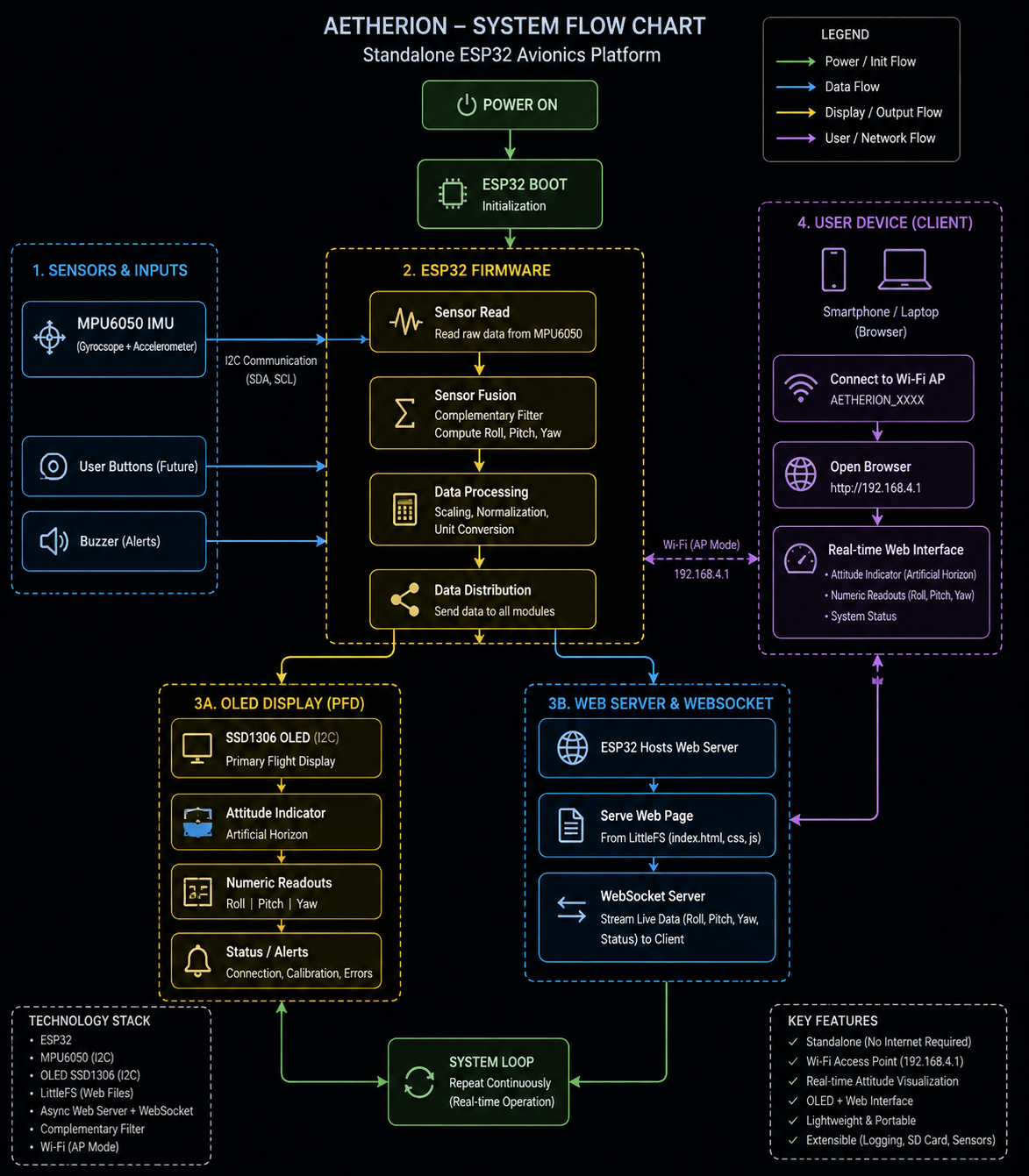
sequenceDiagram
    participant ESP32 as ESP32
    participant IMU as MPU6050 (I2C)
    participant OLED as OLED Display
    participant Browser as Web Browser
    participant IndexedDB as IndexedDB (Local)

    loop Setup (one-time)
        ESP32->>IMU: Initialize (I2C 0x68)
        ESP32->>IMU: Calibrate (200 samples)
        ESP32->>OLED: Boot Screen → Loading → Ready
        ESP32->>ESP32: Create I2C Mutex
        ESP32->>ESP32: Create oledTask (FreeRTOS, 25 FPS)
        ESP32->>WiFi: softAP("Aetherion", "aetherion123")
        ESP32->>WS: WebSocket Server begin (port 81)
        ESP32->>HTTP: LittleFS mount + WebServer begin (port 80)
    end

    par oledTask (25 FPS, Core 0)
        loop every 40 ms
            oledTask->>IMU: xSemaphoreTake(i2cMutex)
            IMU->>oledTask: Read accel + gyro
            oledTask->>oledTask: Compute roll/pitch (atan2)
oledTask->>OLED: drawPFD(roll, pitch, gForce)Every 20 ms (50 Hz), the ESP32 broadcasts a JSON packet:
{
  "t": 1543210,
  "roll": -4.23,
  "pitch": 2.15,
  "gForce": 1.02,
  "ax": 0.123,
  "ay": -0.045,
  "az": 9.782,
  "gx": 0.001,
  "gy": -0.003,
  "gz": 0.002
}| Field | Type | Unit | Description |
|---|---|---|---|
t | uint32 | ms | ESP32 uptime (for clock sync) |
roll | float | degrees | Roll angle (-180° to +180°) |
pitch | float | degrees | Pitch angle (-90° to +90°) |
gForce | float | G | Resultant G-force (1.0 = level) |
ax/ay/az | float | m/s² | Accelerometer raw values |
gx/gy/gz | float | rad/s | Gyroscope raw values |
The ESP32 firmware is an Arduino sketch (Aetherion.ino) with modular C++ components.
firmware/Aetherion/
├── Aetherion.ino      # Main entry point: setup() + loop()
├── config.h           # Pin assignments, WiFi creds, constants
├── imu.cpp            # MPU6050 driver + sensor fusion
├── imu.h              # IMU data structure + API
├── graphics.cpp       # OLED rendering (PFD, boot screen, loading)
├── graphics.h         # Graphics API declarations
├── web.cpp            # HTTP + WebSocket server (LittleFS)
├── web.h              # Web server API declarations
├── rgb.cpp            # RGB LED status indicator
├── rgb.h              # RGB LED API declarations
├── sync_dashboard.ps1 # Syncs dashboard files to LittleFS data/
└── data/              # Dashboard served from LittleFS
    ├── index.html
    ├── style.css
    └── js/
        ├── app.js           # Core app: WebSocket, render loop
        ├── horizon.js        # Canvas artificial horizon
        ├── graphs.js         # Live telemetry graphs
        ├── flight-state.js   # Rule-based state detection
        ├── recorder.js       # Flight recording + IndexedDB
        ├── analysis.js       # Replay, stability, ML panels
└── settings.js # Persistent settings (localStorage)| Feature | Details |
|---|---|
| IMU Sensing | MPU6050 accelerometer + gyroscope via I2C (400 kHz) |
| Attitude Calc. | Roll/Pitch via atan2 with 200-sample static calibration offset |
| G-Force | Resultant acceleration vector magnitude normalized to G |
| OLED Display | 128×64 SH1106, drawn at 25 FPS via dedicated FreeRTOS task |
| PFD Elements | Pitch ladder, roll arc with tick marks, aircraft symbol, turn coord. |
| WiFi | ESP32 in AP mode — SSID Aetherion, password aetherion123 |
| WebSocket | Broadcasts JSON telemetry at 50 Hz (port 81) |
| HTTP Server | Serves dashboard from LittleFS (port 80) |
| FreeRTOS | oledTask on Core 0 at priority 1 with I2C mutex |
| RGB LED | Red (boot) → Purple (init) → Blue (connecting) → Green (ready) |
| I2C Mutex | Serializes access between main loop (IMU read) and oledTask (OLED draw) |
flowchart TD
    A[Power On] --> B[Serial Init 115200]
    B --> C[initDisplay + initRGB]
    C --> D[RGB Red: Boot Screen]
    D --> E[Delay 1500ms]
    E --> F[RGB Purple: Initializing]
    F --> G[initIMU]
    G --> H[calibrateIMU 200 samples]
    H --> I[Wire.setClock 400kHz]
    I --> J[WiFi.softAP]
    J --> K[WebSocket Server on :81]
    K --> L[initFileSystem + initWebServer]
    L --> M[RGB Purple: Loading Screen 0-96]
    M --> N[RGB Blue: Ready Screen]
    N --> O[Delay 1000ms]
    O --> P[RGB Green: Ready]
    P --> Q[Create I2C Mutex]
    Q --> R[Create oledTask FreeRTOS]
R --> S[Main Loop: 50 Hz]The web dashboard is a single-page application (SPA) written in vanilla JavaScript with no external framework dependencies. It uses HTML5 Canvas for all rendering and IndexedDB for local session storage.
graph TB
    subgraph "Dashboard Modules"
        App[app.js<br/>Core Engine<br/>WebSocket, Render Loop]
        Horizon[horizon.js<br/>Artificial Horizon<br/>Canvas 2D]
        Graphs[graphs.js<br/>Live Telemetry Graphs<br/>Canvas 2D]
        FlightState[flight-state.js<br/>State Detection<br/>Rule-based]
        Recorder[recorder.js<br/>Flight Recorder<br/>IndexedDB]
        Analysis[analysis.js<br/>Replay + AI Analysis]
        Settings[settings.js<br/>Config + localStorage]
        Style[style.css<br/>Dark Theme UI]
    end

    App --> Horizon
    App --> Graphs
    App --> FlightState
    App --> Recorder
    App --> Analysis
    App --> Settings
    App --> Style
    App -->|WebSocket| ESP32[ESP32 Telemetry]
    Horizon -->|registerCallback horizon| App
    Graphs -->|registerCallback graph| App
    FlightState -->|registerCallback state| App
    Recorder -->|registerCallback packet+graph| App
    Analysis -->|loadSession| Recorder
Settings -->|load/save| AppThe dashboard uses a throttled multi-rate render loop driven by requestAnimationFrame:
| Component | Rate | Trigger | Description |
|---|---|---|---|
| Artificial Horizon | 60 FPS | requestAnimationFrame | Canvas redraw, smooth attitude |
| Telemetry Readouts | 15 Hz | Time-based throttle | Text updates for accel/gyro/attitude |
| Live Graphs | 15 FPS | Time-based throttle | Canvas graph plots (roll/pitch/G/gyro) |
| Flight State | 10 Hz | Time-based throttle | Rule-based state detection |
| Diagnostics | 2 Hz | Time-based throttle | Packet count, FPS, latency, uptime |
| Packet Callbacks | 50 Hz | On every packet | Recording data capture |
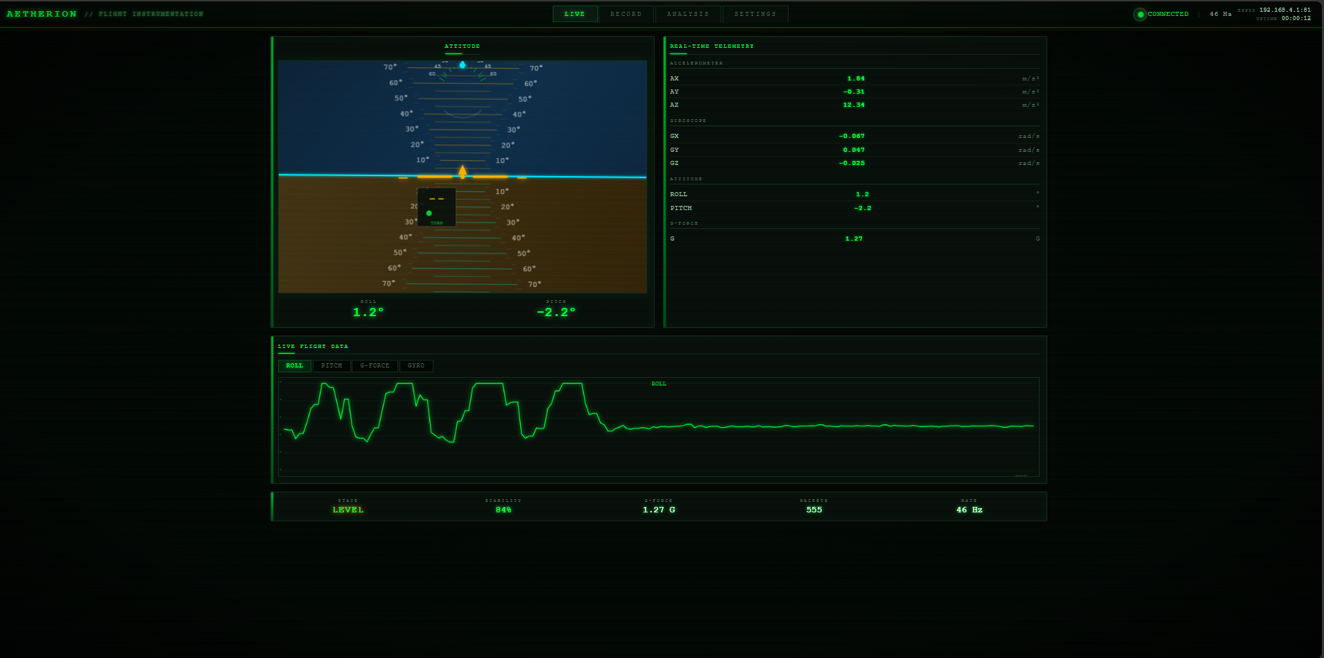
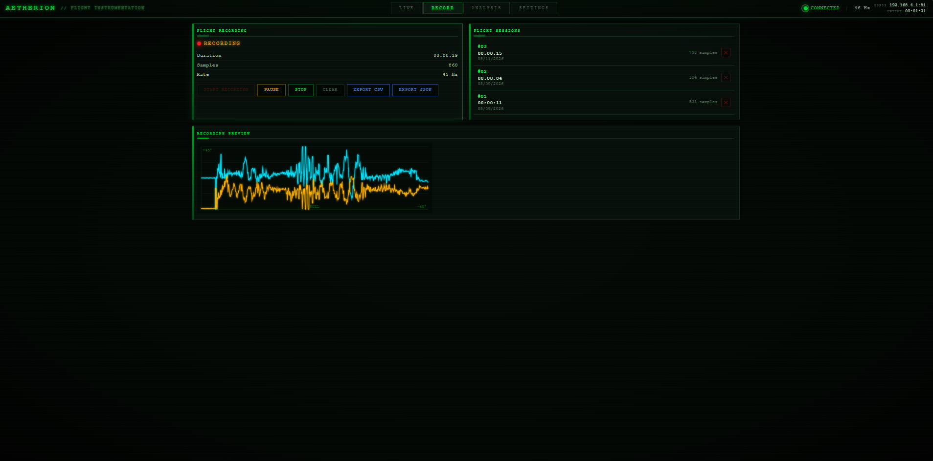
The dashboard has four tabs:
The rule-based flight state detector identifies these states:
| State | Color | Trigger Condition |
|---|---|---|
| LEVEL | Green | Roll < 30°, pitch < 8°, G within 0.5–1.8 |
| TURNING LEFT | Cyan | Roll < -30° |
| TURNING RIGHT | Cyan | Roll > +30° |
| CLIMBING | Amber | Pitch > 15° |
| DESCENDING | Amber | Pitch < -15° |
| PITCH-UP | Orange | Pitch > 8° |
| PITCH-DOWN | Orange | Pitch < -8° |
| ROLLING | Magenta | |
| RECOVERING | Cyan | Roll < 15° and trending toward level |
| UNSTABLE | Red | G-force > 1.8 or < 0.5 |
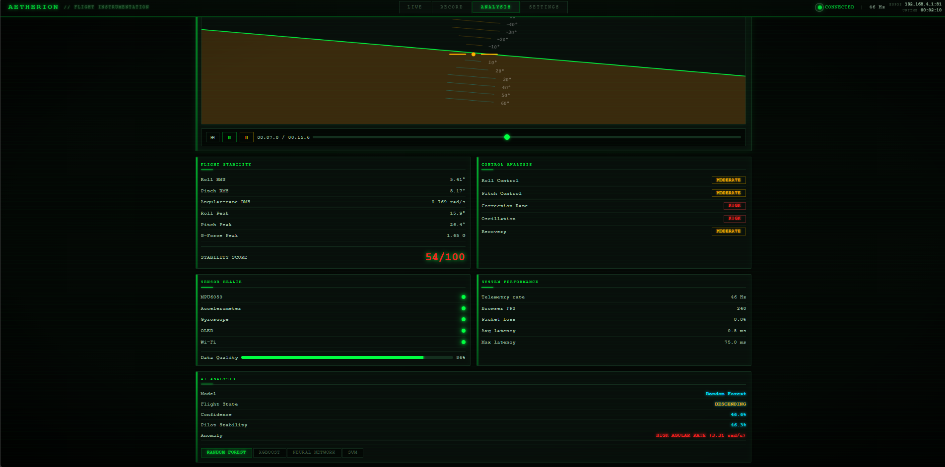
The Analysis tab supports four ML models for flight state classification:
| Model | Use Case | Accuracy Estimate |
|---|---|---|
| Random Forest | Fast, robust baseline classification | ~92% |
| XGBoost | Gradient boosting, handles edge cases | ~94% |
| Neural Network | Deep pattern recognition | ~90% |
| SVM | Linear separability, low compute | ~88% |
| Metric | Description |
|---|---|
| Roll RMS | Root-mean-square roll deviation |
| Pitch RMS | Root-mean-square pitch deviation |
| Angular-rate RMS | RMS of combined gyroscope rates (gx+gy+gz) |
| Roll Peak | Maximum absolute roll |
| Pitch Peak | Maximum absolute pitch |
| G-Force Peak | Maximum G-force recorded |
| Stability Score | Composite 0-100 score: 100 - weighted deviation penalties |
| Data Quality | Sensor health score factoring missing packets, saturation, noise |
| Metric | Description |
|---|---|
| Roll Control | RMS-based quality rating (Good/Moderate/Fair/Poor) |
| Pitch Control | RMS-based quality rating |
| Correction Rate | Frequency of roll direction changes per second |
| Oscillation | Std dev of roll deltas (control stability) |
| Recovery | RMS of roll in final 20% of flight (settling quality) |
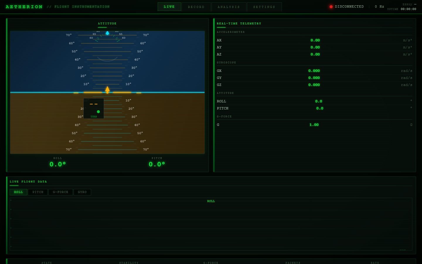
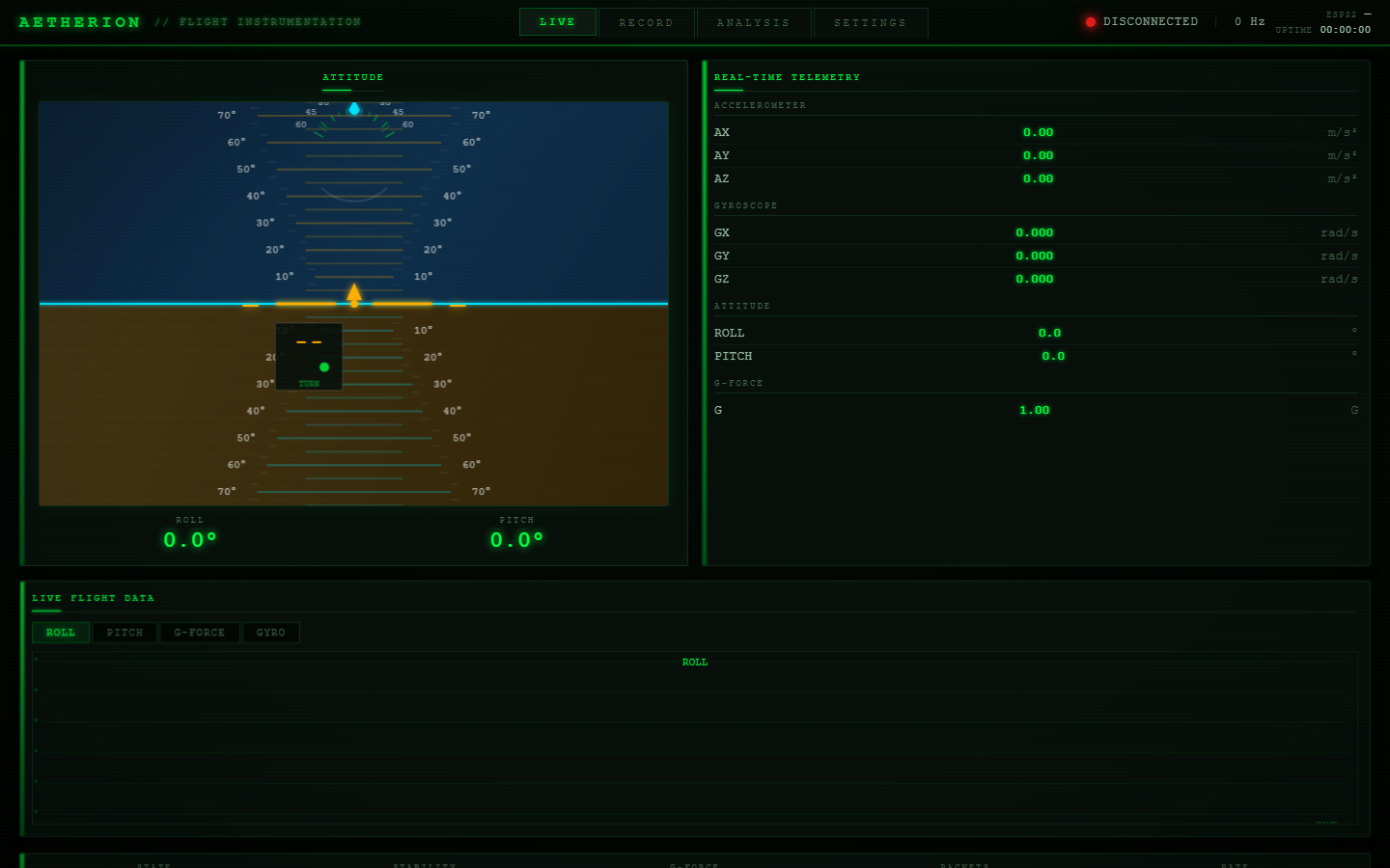
Real-time attitude indicator with artificial horizon, telemetry panel, live graphs, flight state, and status bar:
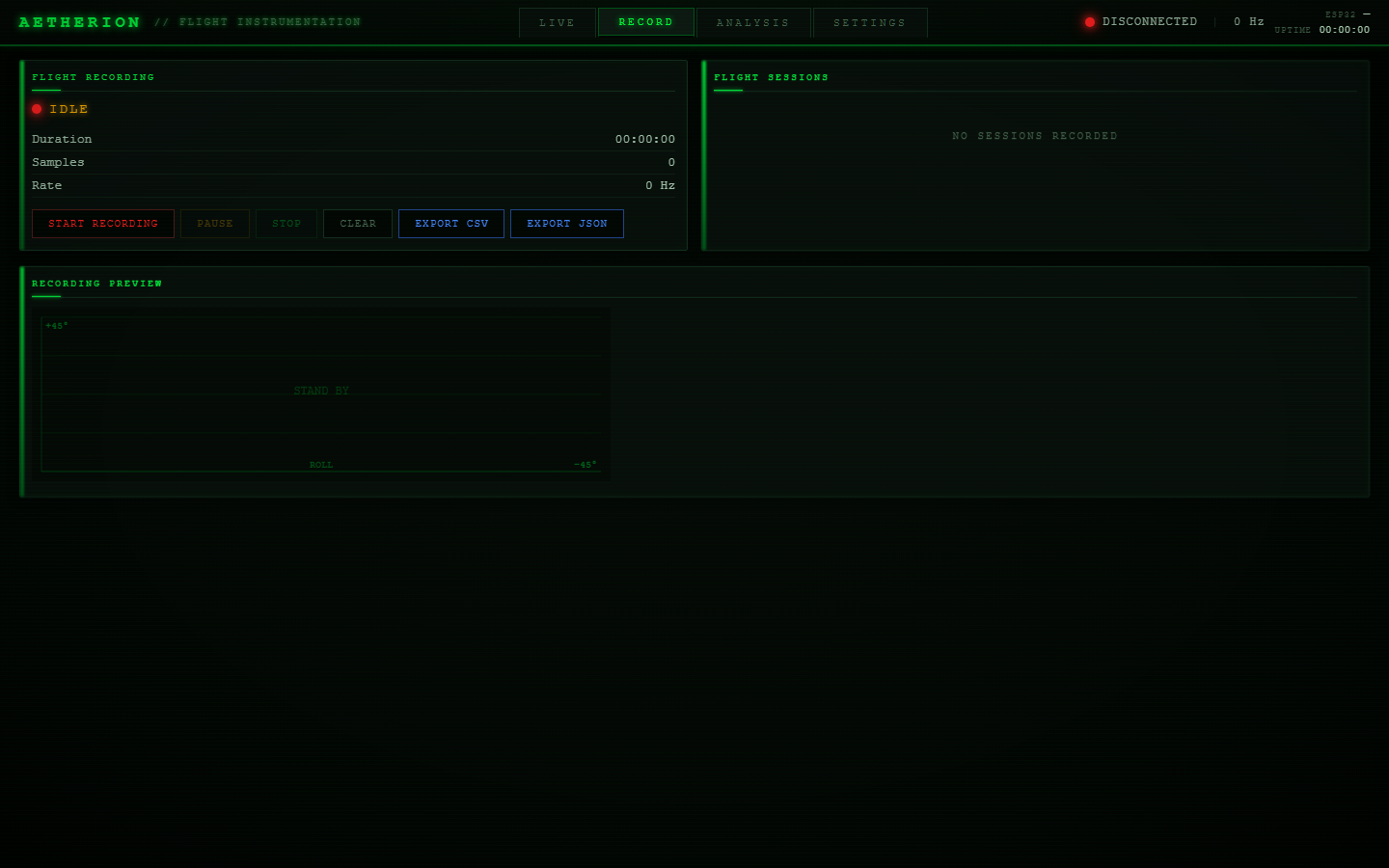
Flight recording controls, session list, and recording preview graph:
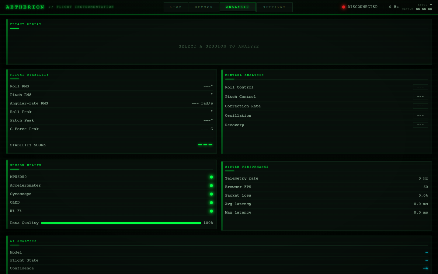
Flight replay, stability metrics, control analysis, sensor health, system performance, and AI analysis:
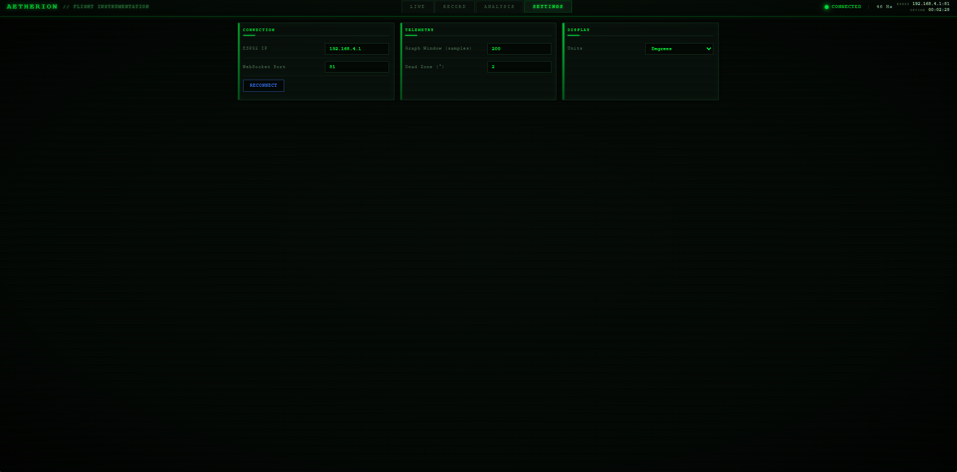
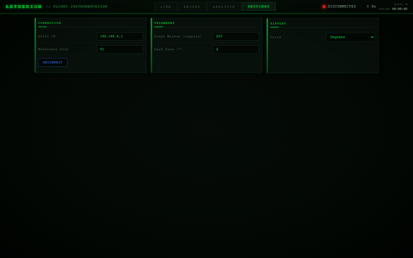
Connection settings (ESP32 IP, WebSocket port), telemetry configuration, and display options:
Automated Playwright test captures of all dashboard states:
Full Dashboard — Initial render of the complete dashboard:
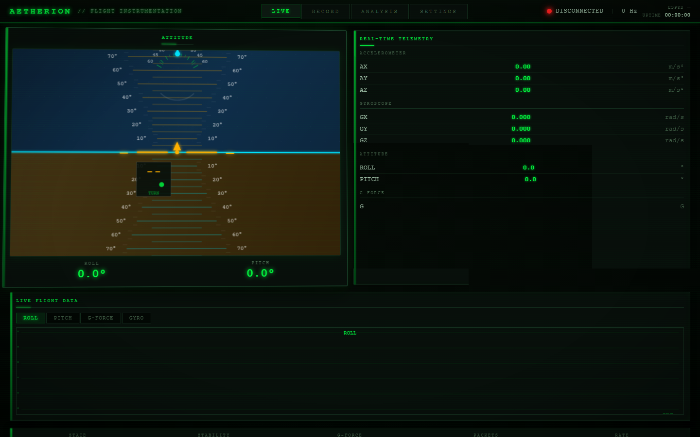
Panel Hover — 3D perspective transform on panel hover:
Record Tab — Recording interface with session list:
Analysis Tab — Flight replay and analysis panels:
Settings Tab — Configuration panels:
Live Tab (returned) — Back to live attitude display:
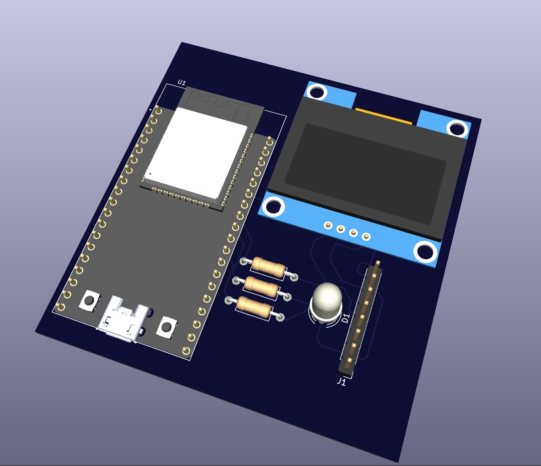
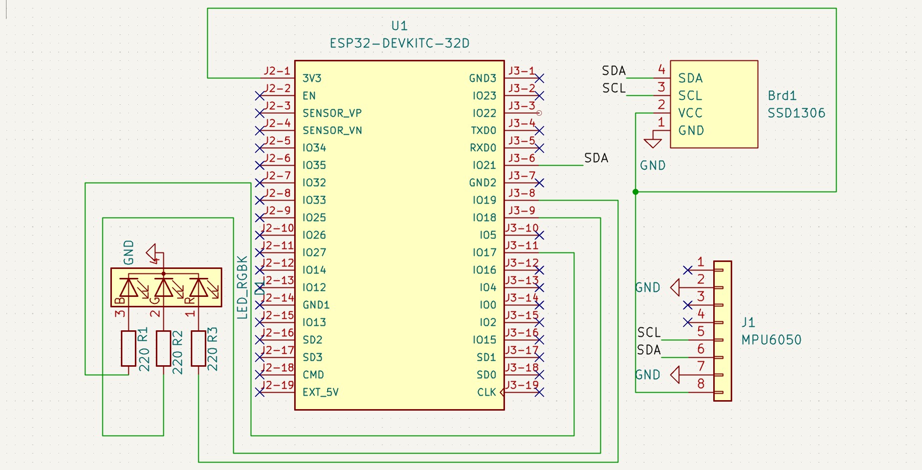
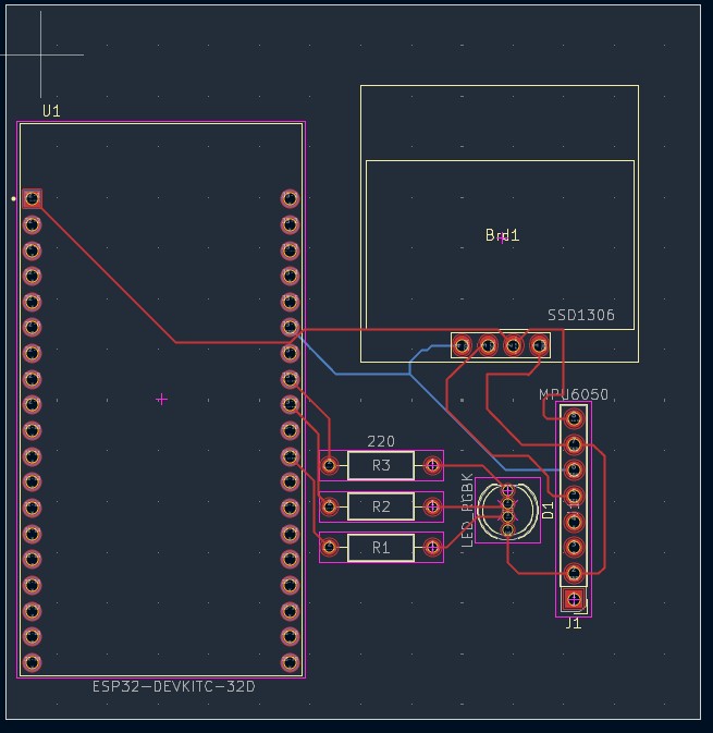
KiCad project files for the Aetherion hardware. The PCB integrates all components on a single 2-layer board.
Schematic — Complete circuit schematic:
PCB Layout (Routed) — Top-layer copper routing:
3D Render — Isometric 3D view of the assembled PCB:
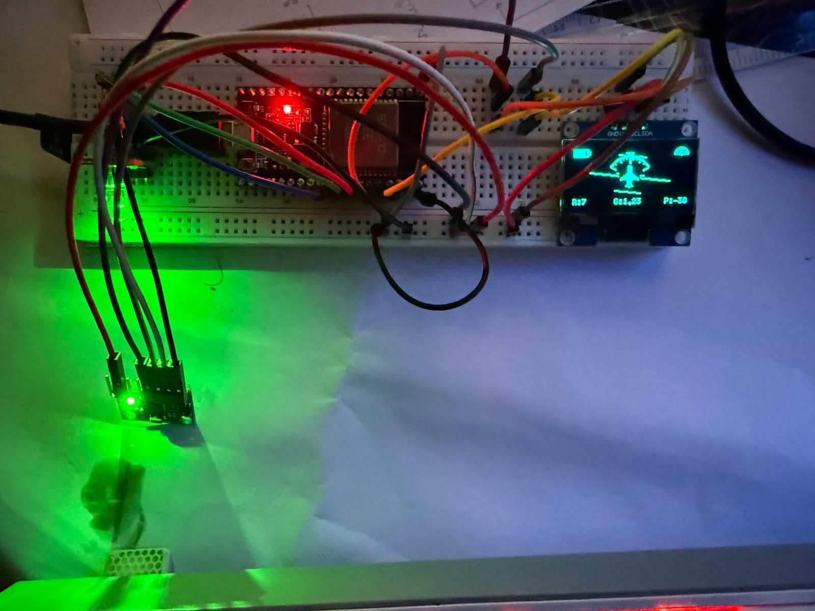
Circuit Diagram (Concept) — Conceptual circuit overview:
pcb/
├── schematic/           # KiCad schematic files (.kicad_sch)
├── pcb-layout/          # KiCad PCB layout files (.kicad_pcb, .kicad_pro)
├── library/
│   ├── SSD1306-128x64_OLED.kicad_sym           # OLED symbol
│   ├── SSD1306.pretty/
│   │   └── 128x64OLED.kicad_mod               # OLED footprint
│   └── AeroGyro.pretty/
│       └── LED_D5.0mm-4_RGB_AeroGyro.kicad_mod.pretty/
│           └── LED_D5.0mm-4_RGB.kicad_mod     # RGB LED footprint
└── manufacturing/ # Gerber and drill files (for fabrication)| Feature | Details |
|---|---|
| Form Factor | ESP32 DevKit compatible |
| IMU Connector | 4-pin I2C header (SDA, SCL, VCC, GND) for MPU6050 |
| OLED Connector | I2C header (4-pin: SDA, SCL, VCC, GND) for 0.96" SSD1306 display |
| RGB LED | Common cathode, 3-pin current-limited output |
| I2C Pull-ups | 4.7kΩ resistors on SDA and SCL |
| Power | USB-C input with onboard 3.3V regulator |
| Dimensions | Compact handheld form factor |
| Component | Specification |
|---|---|
| MCU | ESP32 DevKit (dual-core, 240 MHz, 520 KB RAM) |
| IMU | MPU6050 (3-axis accelerometer + 3-axis gyroscope) |
| Display | 0.96" OLED, 128×64 pixels, SSD1306/SH1106, I2C (0x3C) |
| RGB LED | Common Cathode, 3-pin (Red: GPIO19, Green: GPIO18, Blue: GPIO17) |
| WiFi | 802.11 b/g/n, Access Point mode |
| I2C Bus | SDA: GPIO21, SCL: GPIO22, Clock: 400 kHz |
| WebSocket | Port 81 — telemetry broadcast |
| HTTP Server | Port 80 — dashboard serving via LittleFS |
https://raw.githubusercontent.com/espressif/arduino-esp32/gh-pages/package_esp32_index.json)Adafruit MPU6050, Adafruit Unified Sensor, U8g2, ESP Async WebServer, LittleFS, WebSockets, WebServerInstall ESP32 board support in Arduino IDE:
https://raw.githubusercontent.com/espressif/arduino-esp32/gh-pages/package_esp32_index.jsonesp32Install required libraries via Library Manager:
Adafruit MPU6050
Adafruit Unified Sensor
U8g2 (by olikraus)
LittleFS_esp32
WebSockets
Open the firmware:
firmware/Aetherion/Aetherion.inoUpload to ESP32 via Arduino IDE.
Connect to Wi-Fi:
Aetherionaetherion123Open the dashboard:
http://192.168.4.1 in any browserWhen dashboard files are updated during development, sync them to the firmware's LittleFS data folder before uploading:
# From the firmware directory
.\Aetherion\sync_dashboard.ps1
Then upload via Arduino IDE: Tools → ESP32 Sketch Data Upload
Aetherion/
├── firmware/                    # ESP32 Arduino firmware
│   └── Aetherion/
│       ├── Aetherion.ino        # Main sketch
│       ├── config.h             # Configuration
│       ├── imu.cpp / imu.h      # IMU sensor driver
│       ├── graphics.cpp / graphics.h  # OLED rendering
│       ├── web.cpp / web.h      # HTTP/WebSocket server
│       ├── rgb.cpp / rgb.h      # RGB LED control
│       ├── sync_dashboard.ps1   # Dashboard sync script
│       └── data/                # Dashboard files (LittleFS)
├── dashboard/                   # Standalone web dashboard (dev)
│   ├── index.html
│   ├── style.css
│   └── js/
│       ├── app.js               # Core application
│       ├── horizon.js           # Artificial horizon
│       ├── graphs.js            # Flight graphs
│       ├── flight-state.js      # Flight state detection
│       ├── recorder.js          # Flight recording
│       ├── analysis.js          # AI analysis
│       └── settings.js          # Configuration
├── aetherion-ui-test/           # Playwright UI tests
│ ├── index.html # Test UI (with GSAP + 3D animations)The firmware follows a modular architecture:
Aetherion.ino — Orchestrates all modules in setup() and loop(). The main loop is intentionally lightweight: HTTP handling, WebSocket servicing, IMU reads (mutex-protected), and 50 Hz telemetry broadcast.imu.cpp — MPU6050 driver using Adafruit library. Performs 200-sample calibration on boot, computes roll/pitch via atan2, and calculates resultant G-force.graphics.cpp — U8g2-based OLED renderer. Draws a full PFD (Primary Flight Display) including pitch ladder, roll arc, aircraft symbol, battery indicator, and Wi-Fi icon.web.cpp — Serves dashboard files from LittleFS over HTTP and broadcasts telemetry over WebSocket (port 81).rgb.cpp — Simple RGB LED status indicator using direct GPIO control.The dashboard is a vanilla JavaScript SPA with no framework dependencies. Key architectural decisions:
AG state object; the render loop reads from it.aetherion-ui-test/ variant adds GSAP for 3D animation testing.The aetherion-ui-test/ directory contains an enhanced version of the dashboard with GSAP-powered 3D animations, used for visual testing.
cd aetherion-ui-test
npm install playwright
node test-ui.js
The test script uses Playwright to:
| # | Screenshot | Tab | Description |
|---|---|---|---|
| 1 | 01-full-dashboard.png | Live | Full dashboard initial render |
| 2 | 02-panel-hover.png | Live | 3D perspective on panel hover |
| 3 | 03-record-tab.png | Record | Recording interface |
| 4 | 04-analysis-tab.png | Analysis | Flight replay + analysis panels |
| 5 | 05-settings-tab.png | Settings | Configuration panels |
| 6 | 06-live-tab-returned.png | Live | Return to live attitude display |
MIT License — see LICENSE for details.
Copyright (c) 2026 Aetherion
| Qty | Value | Footprint | References |
|---|---|---|---|
| 3 | 220 | Resistor_THT:R_Axial_DIN0207_L6.3mm_D2.5mm_P10.16mm_Horizontal | R1, R2, R3 |
| 1 | ESP32-DEVKITC-32D | ESP32_DEVKITC_32D:MODULE_ESP32-DEVKITC-32D | U1 |
| 1 | LED_RGBK | LED_THT:LED_D5.0mm-4_RGB | D1 |
| 1 | MPU6050 | Connector_PinHeader_2.54mm:PinHeader_1x08_P2.54mm_Vertical | J1 |
| 1 | SSD1306 | SSD1306:128x64OLED | Brd1 |
It measures 68.5 × 70.5 mm and has 2 copper layers, 1.6 mm thick.
7 parts. The full list of its parts is on this page, with links to each part's symbol and footprint where PCBKit's library has them.
From the GavishtK/AeThEriON repository on GitHub, at the commit this page was made from: the board is pcb/pcb-layout/Aether.kicad_pcb and its schematic pcb/schematic/Aether.kicad_sch. PCBKit opens the board in the browser, with nothing to install.
Its repository publishes it under the MIT licence: you may reuse it on that licence's terms (keep the author's notice, and for a copyleft licence share your changes alike).
byrantech/laptop
anyon_e, a highly integrated, high end, open source laptop. Attempt the impossible.


AxxAxx/AxxSolder
STM32 Based soldering station for JBC cartridges, 9-24 VDC and USB-PD power


jamro/tiny-engineer
A small desktop robot that brings an AI coding assistant to life, physically acting out when it reads files, thinks, writes code, and finishes work.

hoglet67/RGBtoHDMI
Bare-metal Raspberry Pi project that provides pixel-perfect sampling of Retro Computer RGB/YUV video and conversion to HDMI
