2 layers40.5 × 38.8 mm

 gautam-dev-maker/mushak62
It is a Micromouse, maze solving bot.
Mushak pcb is an open-source printed circuit board by gautam-dev-maker, from the gautam-dev-maker/mushak repository on GitHub, published under the MIT licence. It is a 2-layer board of 57.6 × 40 mm with 117 parts on 128 nets, routed with 1,131 tracks and 153 vias.
It is built around the AS5048B-HTSP, DRV8833PWPR and VL53L0CXV0DH/1, with the AMS1117-3.3, MPU-6500 and SFH 3015 FA among its other parts. Its parts include 37 capacitors, 29 resistors, 17 connectors, 7 ICs and 6 diodes. It belongs with the STM32 boards of this library.


Mushak is a micromouse maze solving bot. The aim of this project is to make India's first and smallest half-size micromouse bot. "Mushak" in hindi means "Mouse".
This micromouse consist of a very small coreless motors (6 mm width and 10 mm length) and PCB as it's base . Since coreless motors doesn't provide enough torque for the movements of bot we used gear box to increase the torque.
Mushak is of size 45.7mm x 40.0 mm, which is smaller than similar micromouse using STM32F405RG. We boast of least area consuming micromouse made using STM32 LQFP64 package chips.
 |  |
|---|
.
├── Assets             # Documentation files screenshots, gifs, videos of results
├── firmware           # contains required code for controlling the bot
├── pcb_design         # PCB files made in  kicad 6
├── cad_design         # CAD files of mushak (micromouse)
├── LICENSE            # License for this project
└── README.md          # Contains documentation and information about this project
Further file structure of each folder is given in below sections.
The Mushak PCB design is made on the latest version of KiCAD 6.
Mushak is designed over STM32F405RG microcontroller accomodated with various sensors and drivers for the micromouse.
We designed the smallest micromouse that is based on STM32F405RG microcontroller
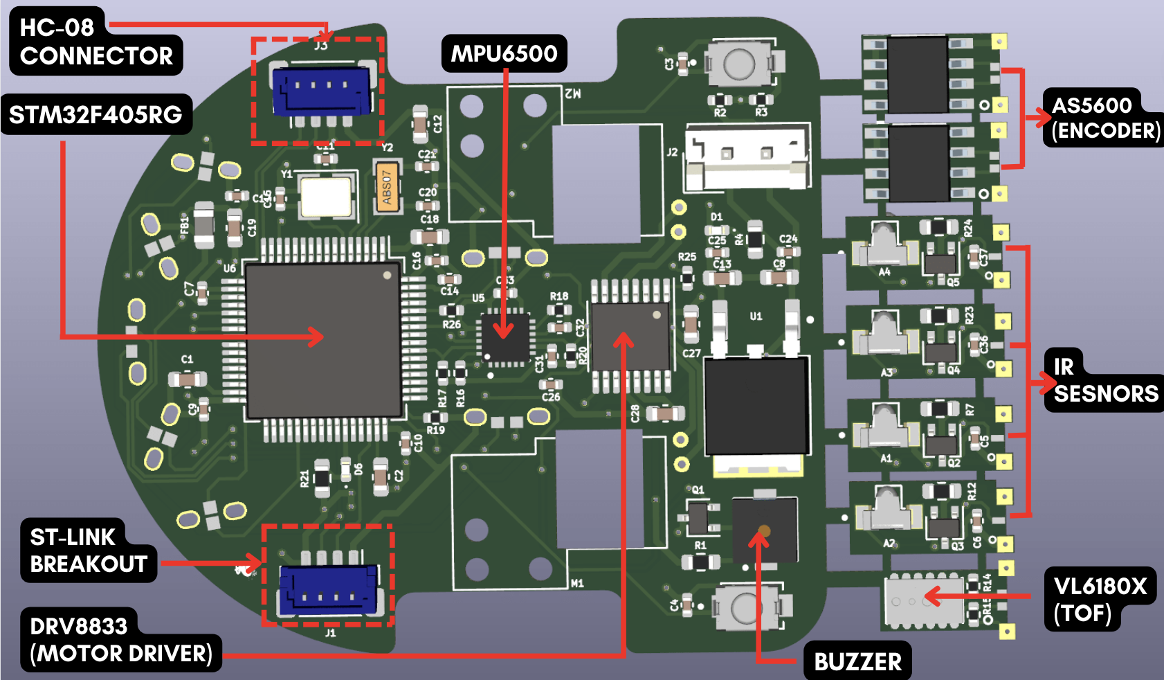
| Components | Description |
|---|---|
| STM32F405RG | Microcontroller |
| VL6180x | ToF sensor4 |
| DRV8833 | Motor Driver |
| MPU6500 | IMU |
| SFH-4045N | Infrared Emitter |
| SFH-3015-FA | Phototransistor (Reciever) |
The IR sensors include majorly two components, IR emitter which emits the Infrared light of a particular wavelength which is not visible with the human eye.
This light gets reflected back from the obstacle present in form of the robot to the photo transistor, when the Infrared light of this perticular wavelength enters the phototransistor device it allows the current to flow from the collector to the emmiter of device. This current flow creates a voltage drop across the resistor connected with the photo transistor and this voltage drop is read by th ADC of the microcontroller which varies as the intensity of light reflected changes. By this way we can determine how far is the obstacle from the robot.
For controlling the intensity of the transmitted light we used N-Channel Mosfet whose gate is controlled by PWM signal given by the microcontroller. By varying the PWM duty cycle we can control the intensity of the transmitted light from IR emmiter by which we can control the distance sensitivity.

Placing IR sensors pose a challenge, and required rigorous testing and brain storming.

As can be seen in the image above we have visualised 2 cell based maze and bot is placed in first cell.
IR1 (blue rays) is pointing to the left mid point of next cell.IR2 (orange rays) is pointing to the left end of current cell.IR3 (pink rays) is pointing to the right end of current cell.IR4 (green rays) is pointing to the right end of current cell.To move the bot in straight line along the diagonal maze pattern , we have considered point 1 and point 2. These two points are the edges of diagonal ends of above pattern . So if bot had to move diagonally we can check for readings at these two points and control the bot accordingly.

The below image shows the pinout of STM32F405RG that we will be using for this project :

Decoupling capacitors of 0.1uF are connected near the vdd pins of STM32. Additional external low and high frequency oscillators are added for precise timing.
Filter circuit is being used for filtering out the analog reference voltage. Additional Debug switches are being added for debugging purposes
We have used H-bridge motor driver which can control two motors at the same time via PWM (pulse width modulation) from the STM32F405RG (microcontroller).
The motor driver can supply 1.5 Amps of current per motor which is enough to power up the coreless motors.
This motor driver keeps the controls terminals from the microcontrolller isolated from noise and high volatages of the motor power supply.

We added a Time of Flight sensor in front of the robot to measure the distance of the obstacle in front from the robot.
This sensor measures the time taken by the light signal to get reflected from the obstacle and then measures the distace of the obstacle from the robot.

We used a BLE(Bluetooth Low Energy) module to communicate to the robot. It is one of the most important modules that is being used in mushak, this bluetooth module will enable us to communicate with the robot and precisely tune it to solve the mazes, additionally it makes debugging easier for us making Mushak user friendly.
The module consumes very less power(since it works on BLE) and works on UART communication to talk with the microcontroller.

To measure the RPM and the distance that the robot has covered we needed a type of encoder feedback. For this we used AS5600 magnetic encoders to measure the amount of rotation of the robot wheel.
The magnetic encoders are mounted in an innovative way due to which no external mounts were required for their placement. Since magnets need to be right infront of the IC of AS5600 to get proper reading, we have taken extra care with mount size and shaft placement.

This sensor gives the feedback of orientaion of the robot. This MEMS based chip has in-built Acclereometer and Gyroscope by which it can determine its orietation with respect to space.
This sensor works on SPI as well as I2C communication protocol but in our case to get the fastest data transfer, we used use SPI communcation.


For routing of the control circuitry we used traces of 0.2mm width and for power connections we used 0.4mm width tracks to ensure fairly high current flow.
Minimalising passive components is a really hard task. So to solve this I properly reffered the application notes and datasheet of stm32f405RG. Moreover the design is well tested on simulation platform.
Efficient placement of components to reduce the size of the PCB. Innovative design to fix sensors and encoders in such a small space.

Since IRs are sensitive to ambient light we required a mechanism to adjust the brighness of IR Emitter. So to do that we used a mosfet based circuit, so brightness can be controlled using PWM.
It was a big challenge to place 90+ SMD and THT components on a small size PCB of just 45.7x40mm size.
CAD design consist of 3D modeling of Bot design.Before design can be made on PCB, we need to check if various other aspects of systems and mechanical design satisfy our requiements. So CAD design form a very important part of our project.
| Parts | Description |
|---|---|
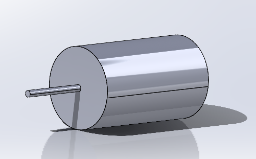 | Motors - This motor has dimensions: Length x Dia. 12 x 6 mm and a shaft lenght of 6mm. |
 | Motor_mount - This is the mount for the motors, which holds the motor, shaft, gears, bearing and magnet.Because of less center-to-center distance between gears, after many iterations this mount was designed. |
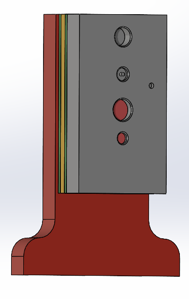 | TOF_mount - This is the mount for TOF sensor, which is placed in front. We have used VL6180x TOF sensor. |
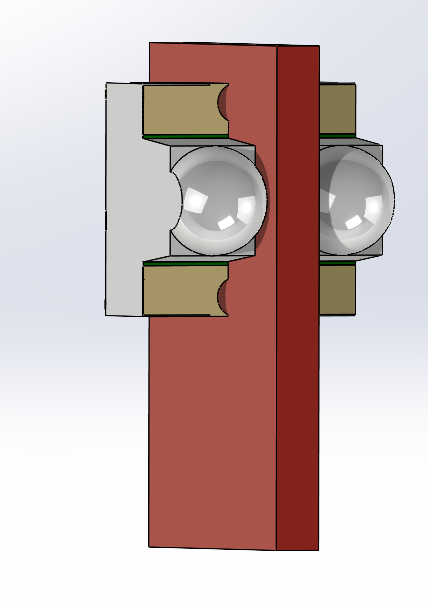 | IR_mounts - These are the mounts for IR sensors placed at specific angles. SFH-3015-FA and SFH-4045N sensors are phototransistors and IR emitters respectively. |
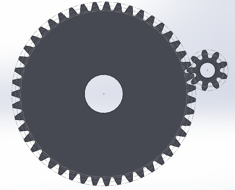 | Gears - The metal gears were extracted from mg90s servos having dimensions: Driving gear: Teeth 9 Pressure Angle - 20º ID - 0.5, OD - 2.14 mm Width 2.46 mm Driven gear: Teeth 47 Pressure Angle 20º ID - 1.5mm, OD - 9.55 mm Width 1.2 mm. Center to center distance is 5.80mm and modulus 0.195 |
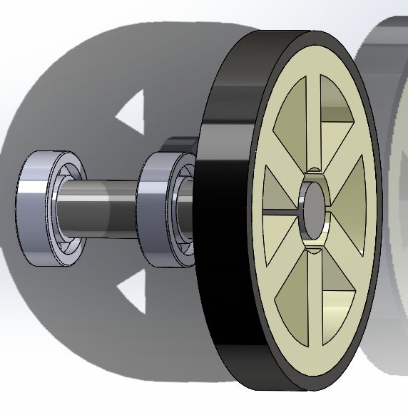 | Bearings, shaft and Wheels - These are the passive components used. Bearings x4 of dimensions: ID x OD 1.5 x 4 mm. Shaft x2 of dimensions: Length x Dia. 15 x 1.5 mm. Wheels with dimensions: ID x OD 1.5 x 12.5 mm. A combination of 2 bearings is used to house the shaft for better stability and lesser Vibrations. |
NOTE :
|  |  |  |
|---|
The firmware for this project is written using STM32-HAL. STM32 HAL consist of bare-metal register address and light weight peripheral libraries giving programmer the full control. For running multiple tasks we are using FreeRTOS. We will be storing the maze in flash memory, since page size is 2 bytes, we need to access 2 bytes at a a time.
The firmware is required to interact with the following external sensors/peripherals:
.
├── Firmware                                # contains required code for controlling the bot
│    ├── Core                               # Contains developer code for sensors and other peripherals
│    │   ├── As5600                         # Driver Api for AS5600
│    │   │   ├── as5600.c                   # Source code for AS5600
│    │   │   └── as5600.h                   # Header file for AS5600
│    │   ├── Ble_logger                     # Bluetooth logger API using UART
│    │   │   ├── ble_logger.c               # Bluetooth logger source code
│    │   │   └── ble_logger.h               # Bluetooth logger header file
│    │   ├── Drv8833                        # Code for Motor Control
│    │   │   ├── drv8833.c                  # Source code for DRV8833
│    │   │   └── drv8833.h                  # Header files for DRV8833
│    │   ├── Inc
│    │   │   ├── FreeRTOSConfig.h           # FreeRTOS configuration file
│    │   │   ├── main.h                     # Main header file
│    │   │   ├── stm32f4xx_hal_conf.h       # STM32 HAL configuration file
│    │   │   └── stm32f4xx_it.h             # contains header of interrupt handlers
│    │   ├── Mpu6500
│    │   │   ├── mpu6500.c                  # Source code for MPU6500 Driver
│    │   │   └── mpu6500.h                  # Header file for MPU6500 Driver
│    │   ├── Peripheral
│    │   │   └── I2c                        # I2C API's handler
│    │   ├── Src
│ │ │ ├── freertos.c # FreeRTOS source codeThe below image shows the pinout of STM32F405RG that we will be using for this project :
So overall 5 ADC channels are required.
So in overall we will require 9 PWM channels.
so In overall 3 GPIO pins are used for getting input and output.
sudo apt-get update
sudo apt-get install -y gcc-arm-none-eabibrew tap ArmMbed/homebrew-formulae
brew install arm-none-eabi-gccST-Link toolchain is required for flashing on STM32 chip.
sudo apt-get update
sudo apt-get -y install stlink-toolsbrew install stlinkgit clone https://github.com/gautam-dev-maker/mushak.git
cd mushak/firmwaremake -j4 # based on no. of logical cores available in your systemmake flash # Currently only st-link support is addedThe License Used for this Project.
| Qty | Value | Footprint | References |
|---|---|---|---|
| 14 | 0.1uF | Capacitor_SMD:C_0402_1005Metric | C3, C4, C5, C7, C9, C10, C14, C16, C24, C30, C32, C33, C40, C41 |
| 11 | 4.7k | Resistor_SMD:R_0402_1005Metric | R2, R3, R5, R8, R9, R10, R14, R15, R25, R32, R33 |
| 10 | 10k | Resistor_SMD:R_0402_1005Metric | R6, R11, R13, R16, R17, R18, R19, R20, R22, R26 |
| 6 | 1uF | Capacitor_SMD:C_0603_1608Metric | C6, C12, C19, C34, C37, C38 |
| 5 | 10uF | Capacitor_SMD:C_0603_1608Metric | C8, C18, C22, C23, C28 |
| 5 | DMN3065LW-7 | Package_TO_SOT_SMD:SOT-323_SC-70 | Q1, Q2, Q3, Q4, Q5 |
| 4 | 100 | Resistor_SMD:R_0603_1608Metric | R7, R12, R23, R24 |
| 4 | SFH_3015_FA | SFH_3015_FA:XDCR_SFH_3015_FA | A1, A2, A3, A4 |
| 4 | SFH_4045N | SFH_4045N:LED_SFH_4045N | D2, D3, D4, D5 |
| 3 | 0.01uF | Capacitor_SMD:C_0402_1005Metric | C17, C26, C31 |
| 3 | 2.2uF | Capacitor_SMD:C_0603_1608Metric | C1, C2, C27 |
| 3 | IR_1 | mushak_mount_footprint:IR_SLAVE_V_04 | J6, J7, J9 |
| 2 | 12pF | Capacitor_SMD:C_0402_1005Metric | C20, C21 |
| 2 | 20pF | Capacitor_SMD:C_0402_1005Metric | C11, C15 |
| 2 | 220 | Resistor_SMD:R_0603_1608Metric | R4, R21 |
| 2 | AS5048B-HTSP | AS5048B-HTSP:SOP65P640X120-14N | U2, U7 |
| 2 | LED | LED_SMD:LED_0402_1005Metric | D1, D6 |
| 2 | SW_Push | TL1015AF160QG:SW_TL1015AF160QG | SW1, SW2 |
| 2 | motor | mushak_mount_footprint:motor | M1, M2 |
| 1 | 10 | Resistor_SMD:R_0603_1608Metric | R1 |
| 1 | 120R | Inductor_SMD:L_0805_2012Metric | FB1 |
| 1 | 150 | Resistor_SMD:R_0402_1005Metric | R31 |
| 1 | 22uF | Capacitor_SMD:C_0603_1608Metric | C13 |
| 1 | 25Mhz | Crystal:Crystal_SMD_3225-4Pin_3.2x2.5mm | Y1 |
| 1 | 32.769kHz | ABS07-32:XTAL_ABS07-32.768KHZ-T | Y2 |
| 1 | 4.7uF | Capacitor_SMD:C_0603_1608Metric | C29 |
| 1 | AMS1117-3.3 | AMS1117-3:SOT229P700X180-4N | U1 |
| 1 | AS5600_1 | mushak_mount_footprint:STAND_HOST_04 | J11 |
| 1 | AS5600_2 | mushak_mount_footprint:STAND_HOST_04 | J13 |
| 1 | AS5600_Left | mushak_mount_footprint:STAND_SLAVE_04 | J4 |
| 1 | AS5600_Right | mushak_mount_footprint:STAND_SLAVE_04 | J5 |
| 1 | BLE_Conn | Connector_JST:JST_SH_BM04B-SRSS-TB_1x04-1MP_P1.00mm_Vertical | J3 |
| 1 | Buzzer | SMT-0440-T-R:XDCR_SMT-0440-T-R | BZ1 |
| 1 | Conn_01x02_Female | Connector_JST:JST_EH_B2B-EH-A_1x02_P2.50mm_Vertical | J2 |
| 1 | Conn_01x04_Male | Connector_JST:JST_SH_BM04B-SRSS-TB_1x04-1MP_P1.00mm_Vertical | J1 |
| 1 | DRV8833PWPR | DRV8833PWPR:IC_DRV8833PWPR | U3 |
| 1 | IR_1 | mushak_mount_footprint:IR_HOST_V_04 | J10 |
| 1 | IR_2 | mushak_mount_footprint:IR_HOST_V_04 | J12 |
| 1 | IR_2 | mushak_mount_footprint:IR_SLAVE_V_04 | J8 |
| 1 | IR_3 | mushak_mount_footprint:IR_HOST_V_04 | J14 |
| 1 | IR_4 | mushak_mount_footprint:IR_HOST_V_04 | J16 |
| 1 | LOGO | mushak_mount_footprint:vjti_logo | G*** |
| 1 | LOGO | mushak_mount_footprint:mooshak_small | G*** |
| 1 | LOGO | mushak_mount_footprint:SRA_logo | G*** |
| 1 | LOGO | mushak_mount_footprint:mooshak | G*** |
| 1 | MPU-6500 | MPU-6500:QFN40P300X300X95-25N | U5 |
| 1 | STM32F405RGTx | Package_QFP:LQFP-64_10x10mm_P0.5mm | U6 |
| 1 | ToF | mushak_mount_footprint:STAND_SLAVE_04 | J17 |
| 1 | ToF | mushak_mount_footprint:STAND_HOST_04 | J15 |
| 1 | VL53L0CXV0DH/1 | VL53L0CXV0DH_1:XDCR_VL53L0CXV0DH_1 | U4 |
It measures 57.6 × 40 mm and has 2 copper layers, 0.6 mm thick.
117 parts, built around the AS5048B-HTSP, DRV8833PWPR, VL53L0CXV0DH/1 and AMS1117-3.3. The full list of its parts is on this page, with links to each part's symbol and footprint where PCBKit's library has them.
From the gautam-dev-maker/mushak repository on GitHub, at the commit this page was made from: the board is pcb_design/mushak_pcb.kicad_pcb and its schematic pcb_design/AS5048_left.kicad_sch. PCBKit opens the board in the browser, with nothing to install.
Its repository publishes it under the MIT licence: you may reuse it on that licence's terms (keep the author's notice, and for a copyleft licence share your changes alike).


tadzio8425/Micromouse
Micromouse developed by the IEEE Robotics and Automation Society chapter of the Universidad de Los Andes, Bogotá (2023-2024).

P1nkman9/High_DoF_Robotics_End-Effector_for_Industrial_Application
UCL_Final_Year_Project

matthieuvigne/MiAM_robotics
Generic repo for robotic projects with the former MiAM Eurobot team !


