2 layers47.2 × 69.6 mm
Sdmplayerv0.01
SL-RU/sdmplayer
This is sources of my DIY music player based on STM32 MCU and VS1053 codec
78 parts26MIT

 gatasConspicuity/gatas26
eConspicuity with support for ADS-L, OGN, FLARM, FANET for General Aviation
OpenACE V0.0.2 is an open-source printed circuit board by gatasConspicuity, from the gatasConspicuity/gatas repository on GitHub, published under the GPL-3.0 licence. It is a 2-layer board of 87 × 84.1 mm with 80 parts on 81 nets, routed with 739 tracks and 163 vias.
It is built around the LM3671MF-3.3, SC0918 and S8050. Its parts include 24 resistors, 19 connectors, 16 capacitors, 7 ICs and 1 transistor. It belongs with the RP2040 boards of this library.


NOTE:: This PCB design contains few, but not all changes from the V0.0.1 version (not published) and is still work in progress.
NOTE:: Help wanted. If you have some PCB experence and also into flying, I would love to have some help with this!
Except for the memory card and the items fixed below, all items on this PCB has been verified to be working on the prototype board V0.0.1
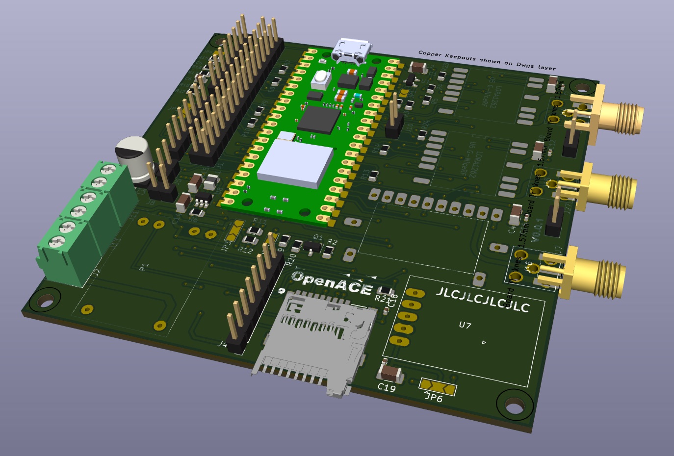
To open and work on the PCB you need to install KiCAD KiCAD is an openSource schema and PCB design program which was used to design the PCB and to manufacture the PCB.
| Item | Comment | Status |
|---|---|---|
| S8050 has pin 1 and 2 rotated | fixed | |
| LM3671 incorrectly has PIN 4 to GND | fixed | |
| Flash Card is rotated | no comment... | fixed |
| Connection terminals too close | fixed | |
| Remove breakout header | Safe space, not needed anyways... | |
| Use PICO 2350 (need to wait for WIFI version) | Faster CPU, floating point. | |
| Add “Port” number on the PCB | Might make people understand the board better | |
| Use MIC5219 instead of LM3671 | Price point, but need to validate | |
| Add silkscreen markers so pins are more clear | ||
| Add solder jumpers show what is the 5V side and 3.3V side | ||
| Put Positive and negative Battery connection to opposite end of the board | to avoid longer connecte wires on the battery which can lead to shortcuts when assembling/working on the board | |
| Battery charger is slightly too wide in length TP4056 | ||
| Re-organize board: Pico in center facing ‘up’ with 868Mhz on left and right. GPS and ADSB under the 868Mhz | This will make the antenna more separate and make the board not so wide. Any other ideas? | |
| Double switch as a PCB board item to have a battery charge, off and battery charge-on position | Conserve battery, makes it easer to solder the board eg less wires and less chance of mistakes | |
| Add + and - of battery connection to opposite of PCB instead of next to eachother | To ensure people create short wires on the battery to prevent shortcuts during testing/developing | |
| GPS chip should be able to be both internal and external | ||
| AHRS on the board? | people seem to want that.. |
| Qty | Value | Footprint | References |
|---|---|---|---|
| 11 | 33 | Resistor_SMD:R_0805_2012Metric | R7, R8, R9, R10, R11, R12, R13, R14, R21, R23, R24 |
| 7 | 100nF | Capacitor_SMD:C_0402_1005Metric | C2, C5, C12, C13, C16, C18, C20 |
| 7 | 10uF | Capacitor_SMD:C_1206_3216Metric | C1, C4, C10, C11, C14, C15, C19 |
| 4 | 220 | Resistor_SMD:R_0805_2012Metric | R15, R16, R17, R20 |
| 4 | MountingHole | MountingHole:MountingHole_2.7mm | H1, H2, H3, H4 |
| 3 | 10K | Resistor_SMD:R_0805_2012Metric | R2, R3, R6 |
| 3 | Conn_Coaxial | Connector_Coaxial:SMA_Samtec_SMA-J-P-X-ST-EM1_EdgeMount | J14, J15, J16 |
| 3 | Conn_Coaxial | Connector_Coaxial:SMA_Amphenol_132203-12_Horizontal | J7, J25, J27 |
| 3 | LED | Connector_PinHeader_2.54mm:PinHeader_1x02_P2.54mm_Vertical | J8, J9, J12 |
| 3 | SolderJumper_3_Open | Jumper:SolderJumper-3_P2.0mm_Open_TrianglePad1.0x1.5mm | JP2, JP3, JP6 |
| 2 | 1K | Resistor_SMD:R_0805_2012Metric | R19, R22 |
| 2 | 750 | Resistor_SMD:R_0805_2012Metric | R1, R18 |
| 2 | Conn_01x08_Pin | Connector_PinHeader_2.54mm:PinHeader_1x08_P2.54mm_Vertical | J3, J4 |
| 2 | G-NiceRF / LORA1262 | gnicerf:lora1262 | U5, U6 |
| 1 | 2.2uH | Inductor_SMD:L_1008_2520Metric | L1 |
| 1 | 220uF | Capacitor_SMD:CP_Elec_6.3x7.7 | C3 |
| 1 | 22uF | Capacitor_SMD:C_0805_2012Metric | C6 |
| 1 | 470K | Resistor_SMD:R_0805_2012Metric | R4 |
| 1 | 680K | Resistor_SMD:R_0805_2012Metric | R5 |
| 1 | Battery | TerminalBlock_Phoenix:TerminalBlock_Phoenix_PT-1,5-2-3.5-H_1x02_P3.50mm_Horizontal | J13 |
| 1 | Conn_01x07_Pin | Connector_PinHeader_2.54mm:PinHeader_1x07_P2.54mm_Vertical | J6 |
| 1 | Conn_02x16_Odd_Even | Connector_PinHeader_2.54mm:PinHeader_2x16_P2.54mm_Vertical | J1 |
| 1 | GNS Module | GNS:GNS5892R1 | GNS5892R1 |
| 1 | GPS Module M8N | misc:gps_module_1 | U7 |
| 1 | LED | Jumper:SolderJumper-2_P1.3mm_Open_TrianglePad1.0x1.5mm | JP5 |
| 1 | LM3671MF-3.3 | Package_TO_SOT_SMD:SOT-23-5 | U8 |
| 1 | LM4040DBZ-3 | Package_TO_SOT_SMD:SOT-23 | U1 |
| 1 | LOGO | LOGO | G*** |
| 1 | MicroSD card (TF card) | ul_GT-TF003-H0185-02:CONN9_0185-02_GSW | U9 |
| 1 | PICO Power | Jumper:SolderJumper-2_P1.3mm_Open_TrianglePad1.0x1.5mm | JP1 |
| 1 | Power 5V | TerminalBlock_Phoenix:TerminalBlock_Phoenix_PT-1,5-2-3.5-H_1x02_P3.50mm_Horizontal | J2 |
| 1 | Power Module / Battery Charger | misc:TP4056-charger-module | P1 |
| 1 | Power Switch | TerminalBlock_Phoenix:TerminalBlock_Phoenix_PT-1,5-2-3.5-H_1x02_P3.50mm_Horizontal | J11 |
| 1 | S8050 | Package_TO_SOT_SMD:SOT-23 | Q1 |
| 1 | SC0918 | SC0918:MODULE_SC0918 | U2 |
| 1 | Speaker | Jumper:SolderJumper-2_P1.3mm_Open_TrianglePad1.0x1.5mm | JP4 |
| 1 | Speaker | Connector_PinHeader_2.54mm:PinHeader_1x02_P2.54mm_Vertical | J5 |
| 1 | ~{RUN} | Connector_PinHeader_2.54mm:PinHeader_1x02_P2.54mm_Vertical | J10 |
SL-RU/sdmplayer
This is sources of my DIY music player based on STM32 MCU and VS1053 codec

FeruzTopalov/spoke
Standalone LoRa-based real-time off-grid relative GPS navigation for group of up to 5 people. Improved version of LRNS Eleph


volium/PowerSupply_lm3671
Schematic and PCB design of 3.3 V and 600 mA power supply using LM3671

WeBuildAnything/Wireless-Media-Control-Mouse
The IMU sensor uses the MPU6050 library by Electronic Cats.

BitDogLab/BitDogLab
Open-source educational hardware for embedded systems, programming, electronics, and physical computing.

c0de111/tinta
Battery-powered e-paper sign: room signage, sensor graphs, home automation, or anything over Wi-Fi. Wakes by real-time clock, NFC tap, or button. Raspberry Pi Pico W firmware, custom PCB, and 3D-printed case included.
It measures 87 × 84.1 mm and has 2 copper layers, 1.6 mm thick.
80 parts, built around the LM3671MF-3.3, SC0918 and S8050. The full list of its parts is on this page, with links to each part's symbol and footprint where PCBKit's library has them.
From the gatasConspicuity/gatas repository on GitHub, at the commit this page was made from: the board is OpenACE V0.0.2/OpenACE V0.0.2.kicad_pcb and its schematic OpenACE V0.0.2/OpenACE V0.0.2.kicad_sch. PCBKit opens the board in the browser, with nothing to install.
Its repository publishes it under the GPL-3.0 licence: you may reuse it on that licence's terms (keep the author's notice, and for a copyleft licence share your changes alike).