
2 layers103.8 × 50 mm
Galagino pcb set
harbaum/galagino
A Galaga, Pac-Man and Donkey Kong arcade emulator for the ESP32
26 parts558
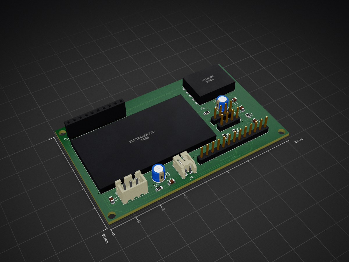
 gargsrishtii/TankSync-RX
2-layer receiver PCB for TankSync wireless monitoring system — ESP32 + LoRa, KiCad 10.0
Project1 is an open-source printed circuit board by gargsrishtii, from the gargsrishtii/TankSync-RX repository on GitHub. It is a 2-layer board of 81 × 50 mm with 20 parts on 41 nets, routed with 377 tracks and 60 vias.
It is built around the ESP32-DEVKITC-VE. Its parts include 7 capacitors, 6 connectors, 5 resistors and 2 ICs. It belongs with the radio and wireless boards and the ESP32 boards of this library.
2-layer receiver board for a wireless tank monitoring system, built around the ESP32-DevKitC-VE and RYLR998 LoRa module. Designed in KiCad 10.0.
TankSync RX is the receiver-side PCB of a LoRa-based wireless monitoring system. It receives sensor data transmitted over 868/915 MHz LoRa and processes it via an ESP32 for display and relay control.
Key features:
| Parameter | Value |
|---|---|
| Board size | 80 × 50 mm |
| Layers | 2 (F.Cu + B.Cu) |
| PCB thickness | 1.6 mm |
| Design tool | KiCad 10.0 |
| ERC status | 0 errors, 0 warnings |
| DRC status | 0 errors, 0 unconnected |
| Gerbers | Exported and verified |
See
/schematic/TankSync_RX_Schematic.pdffor the full schematic.
Key design decisions:
| Ref | Qty | Value / Part | Package | Description |
|---|---|---|---|---|
| U1 | 1 | RYLR998 | Castellated 5-pin SMD | REYAX 868/915MHz LoRa UART module |
| U2 | 1 | ESP32-DEVKITC-VE | 38-pin THT dual row | Espressif ESP32 dev board |
| C1 | 1 | 10µF | 0805 SMD | Power rail decoupling |
| C2 | 1 | 47µF | 0805 SMD | Power rail decoupling |
| C3, C4 | 2 | 100µF | Radial THT D5.0mm P2.5mm | Bulk decoupling — must stay THT |
| C6, C7, C8 | 3 | 100nF | 0805 SMD | ESP32 pin decoupling |
| R2 | 1 | 10KΩ | 0805 SMD | LORA_RST pull-up |
| R3 | 1 | 470Ω | 0805 SMD | LED data line series resistor |
| R4, R5, R6 | 3 | 330Ω | 0805 SMD | Status LED current limiters |
| J1 | 1 | Berg 13-pin | PinHeader 1x13 2.54mm | Relay expansion header |
| J2 | 1 | Berg 10-pin | PinHeader 1x10 2.54mm | Relay expansion header |
| J3 | 1 | 1.3" OLED | PinHeader 1x04 2.54mm | OLED display connector |
| J4 | 1 | JST PH 2-pin | JST PH S2B 2.0mm | Power input |
| J5 | 1 | JST XH 3-pin | JST XH B3B 2.5mm | External data connector |
| J6 | 1 | LED Panel | PinHeader 1x04 2.54mm | LED panel connector |
tanksync-pcb/
├── README.md
├── LICENSE
├── images/
│   └── 3D view.png
|   ├── TankSync-rx.png
|   ├── pcb-layout.png
├── gerbers/
│   └── TankSync_RX_Gerbers.zip
├── bom/
│   └── Project1.csv
└── kicad/
    ├── Project1.kicad_pro
    ├── Project1.kicad_sch
    ├── Project1.kicad_pcb
└── Project1.netThe /gerbers/ folder contains the complete Gerber set ready for fabrication:
| File | Layer |
|---|---|
| Project1-F_Cu.gbr | Front copper |
| Project1-B_Cu.gbr | Back copper |
| Project1-F_Silkscreen.gbr | Front silkscreen |
| Project1-B_Silkscreen.gbr | Back silkscreen |
| Project1-F_Mask.gbr | Front solder mask |
| Project1-B_Mask.gbr | Back solder mask |
| Project1-F_Paste.gbr | Front solder paste |
| Project1-B_Paste.gbr | Back solder paste |
| Project1-Edge_Cuts.gbr | Board outline |
| Project1-job.gbrjob | Gerber job file |
Recommended fab services: JLCPCB, PCBWay, OSH Park (all accept this Gerber format directly).
This design uses two custom KiCad components from my public library:
MyLibrary:RYLR998_Castellated_5P — REYAX RYLR998 LoRa moduleMyLibrary:ESP32-DEVKITC-VE — Espressif ESP32-DevKitC-VE dev boardTo open this project in KiCad, you need to add the custom library first: 👉 gargsrishtii/kicad-parts-library
Follow the installation instructions in that repo's README before opening the .kicad_sch or .kicad_pcb files.
This hardware design is released under CERN-OHL-P v2 (Permissive Open Hardware License). Free to use, modify, and manufacture — no share-alike requirement. See LICENSE for full terms.
Part of the TankSync wireless monitoring system project. Custom KiCad library: gargsrishtii/kicad-parts-library
| Qty | Value | Footprint | References |
|---|---|---|---|
| 3 | 100nF | Capacitor_SMD:C_0805_2012Metric | C6, C7, C8 |
| 3 | 330ohm | Resistor_SMD:R_0805_2012Metric | R4, R5, R6 |
| 2 | 100uF | Capacitor_THT:CP_Radial_D5.0mm_P2.50mm | C3, C4 |
| 1 | 1.3 inches_OLED | Connector_PinHeader_2.54mm:PinHeader_1x04_P2.54mm_Vertical | J3 |
| 1 | 10K | Resistor_SMD:R_0805_2012Metric | R2 |
| 1 | 10uF | Capacitor_SMD:C_0805_2012Metric | C1 |
| 1 | 470ohm | Resistor_SMD:R_0805_2012Metric | R3 |
| 1 | 47uF | Capacitor_SMD:C_0805_2012Metric | C2 |
| 1 | Berg10Pins | Connector_PinHeader_2.54mm:PinHeader_1x10_P2.54mm_Vertical | J2 |
| 1 | Berg13Pins | Connector_PinHeader_2.54mm:PinHeader_1x13_P2.54mm_Vertical | J1 |
| 1 | ESP32-DEVKITC-VE | MyLibrary:ESP32-DEVKITC-VE | U2 |
| 1 | JST Input Power | Connector_JST:JST_PH_S2B-PH-K_1x02_P2.00mm_Horizontal | J4 |
| 1 | JST_3PIN_2.54MM | Connector_JST:JST_XH_B3B-XH-A_1x03_P2.50mm_Vertical | J5 |
| 1 | Led_Panel | Connector_PinHeader_2.54mm:PinHeader_1x04_P2.54mm_Vertical | J6 |
| 1 | RYLR998 | MyLibrary:RYLR998_Castellated_5P | U1 |
harbaum/galagino
A Galaga, Pac-Man and Donkey Kong arcade emulator for the ESP32

RParkerE/OpenSilicon
OpenSilicon enables DIY semiconductor fabrication with open-source guides for building IC equipment at home. The project includes BOMs, 3D files, firmware, and PDKs, supporting makers and researchers in chip fabrication.

cole8888/SRNE-Solar-Charge-Controller-Monitor
Read data from SRNE solar charge controllers.


ste2425/PSP-Bluetooth-AVConnector
An AV-Out Breakout library for the PSP. Providing Kicad symbols and footprints to interface with the PSP 2/3K AVOut socket (also known as the TVOut socket)

It measures 81 × 50 mm and has 2 copper layers, 1.6 mm thick.
20 parts, built around the ESP32-DEVKITC-VE. The full list of its parts is on this page, with links to each part's symbol and footprint where PCBKit's library has them.
From the gargsrishtii/TankSync-RX repository on GitHub, at the commit this page was made from: the board is kicad/Project1.kicad_pcb and its schematic kicad/Project1.kicad_sch. PCBKit opens the board in the browser, with nothing to install.
Its repository states no licence, so its author keeps all rights: ask gargsrishtii before reusing the design.