2 layers65 × 28 mm
BMS Cell Module
stuartpittaway/diyBMS
Do it yourself battery management system for Lithium ion battery packs/cells
37 parts676GPL-3.0

 garethhcoleman/IsoISE-feather
Hardware files for IsoISE feather board
IsoISE feather is an open-source printed circuit board by garethhcoleman, from the garethhcoleman/IsoISE-feather repository on GitHub, published under the GPL-3.0 licence. It is a 2-layer board of 50.8 × 22.9 mm with 119 parts on 43 nets, routed with 292 tracks and 16 vias.
It is built around the MTU1D0305MC, MCP3221A5-E and TL072, with the ADUM1250ARZ among its other parts. Its parts include 11 resistors, 9 capacitors, 6 ICs, 3 connectors and 2 inductors. It belongs with the microcontroller boards boards of this library.


##Hardware files for IsoISE feather board
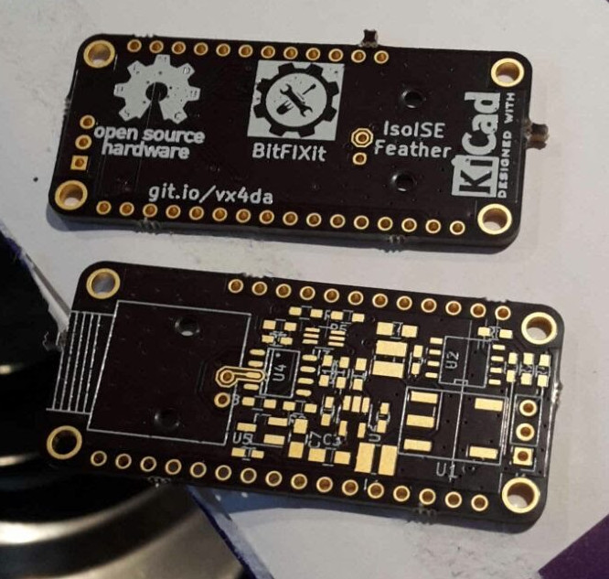 In this repo you will find all the design files; I hope it is everything you need to reproduce and hopefully improve my work.
This circuit is heavily based on wonderful work by Ryan Edwards at sparkyswidgets.com.
I emailed Ryan because I wanted to ask if he was happy for me to just make his isoion project, which is not strictly necessary but I think is good manners. He gave me his blessing to go ahead. I thought it was especially important to do this since he was selling his projects (although not this one, my orignal motivation for making it) and I wasn't then intending to modify his design. Subsequently I took the bull by the horns and dove into (partially!) understanding and modifying his designs, so I took his more advanced ion selective electrode interface project and went from there.
As you can see by comparing our circuits, I copied his design for the isolated I2C based ADC and digital pot, applied to a TL072 JFET op-amp front end. The only significant changes I made were to replace the isolated power supply and separate -5V generator with an isolated supply able to generate +-5V from 3.3V. I did this because the original ADUM6010 datasheet does not recommend the combination of VIN=3.3V and VOUT=5V.
The PCB layout is my own work, my first ever board produced and already I can see issues!! The guard rings around the signal input pin are very tightly spaced making soldering difficult - in a future revision I will increase the spacing there. I somehow ended up skipping the reference R3 - so there are 11 resistors on board numbered R1-R12. Again, I'll correct this in future revisions. I didn't pay much attention to silkscreen component references so assembly will require reference to the board layout in Kicad....
I'm following Dave Jones' OSHW logo and definition: https://www.eevblog.com/oshw/
S = Schematic - Included P = PCB - Included F = Firmware and/or software - TO BE DONE M = Mechanical CAD files - NOT APPLICABLE D = Design Documentation - This document B = Bill Of Materials - Included C = License used allows for commercial use - YES
I've used open software to produce these files: Kicad 4.0.7, LibreOffice 4.3 and Remarkable 1.87
You can order the revision 1 board at OSH Park. Additionally, a shared basket of almost all the required components is available at digikey.
Licensed under the Creative Commons Attribution-ShareAlike 3.0 Unported license, following the license of the originating project.
| Qty | Value | Footprint | References |
|---|---|---|---|
| 5 | 0.1uF | kicad-library:C_0603_HandSoldering | C1, C2, C5, C6, C9 |
| 3 | 10uF | Capacitors_SMD:C_0805_HandSoldering | C3, C4, C7 |
| 3 | 3K | Resistors_SMD:R_0603_HandSoldering | R1, R2, R9 |
| 3 | 4.7K | Resistors_SMD:R_0603_HandSoldering | R4, R5, R6 |
| 2 | 100K | Resistors_SMD:R_0603_HandSoldering | R8, R10 |
| 2 | 10uH | kicad-library:Inductor_Murata_8200 | L1, L2 |
| 1 | 10K | Resistors_SMD:R_0603_HandSoldering | R7 |
| 1 | 1K | Resistors_SMD:R_0603_HandSoldering | R11 |
| 1 | 220pF | kicad-library:C_0603_HandSoldering | C8 |
| 1 | 500R | Resistors_SMD:R_0603_HandSoldering | R12 |
| 1 | ADUM1250ARZ | SMD_Packages:SOIC-8-N | U2 |
| 1 | BNC | kicad-library:BNC_Socket_Gmod | J2 |
| 1 | Conn_01x03 | Pin_Headers:Pin_Header_Straight_1x03_Pitch2.54mm | J1 |
| 1 | FEATHER | kicad-library:FeatherWing | J3 |
| 1 | LOGO | wq-boardv2:oshw_all_13mm | G*** |
| 1 | LOGO | wq-boardv2:bitfixitlogoflipped | G*** |
| 1 | MCP3221 | TO_SOT_Packages_SMD:SOT-23-5_HandSoldering | U6 |
| 1 | MCP4017 | TO_SOT_Packages_SMD:SOT-363_SC-70-6_Handsoldering | U3 |
| 1 | MTU1D0305MC | kicad-library:5pinMTU | U1 |
| 1 | REF3130 | TO_SOT_Packages_SMD:SOT-23_Handsoldering | U5 |
| 1 | TL072 | kicad-library:SOP-8L | U4 |
The 33 most common of 119 parts.
stuartpittaway/diyBMS
Do it yourself battery management system for Lithium ion battery packs/cells

omarKmekkawy/RaspberryPi_HardwareTestingAutomation_Shield
A Raspberry Pi Shield for Hardware Testing Automation


cardonabits/haxo-hw
Haxophone, an electronic musical instrument that resembles a saxophone


Th3Link/tanklevel
This project provides a solution for measuring the liquid level in tanks, such as rainwater tanks, using the TL-136 pressure sensor.

It measures 50.8 × 22.9 mm and has 2 copper layers, 1.6 mm thick.
119 parts, built around the MTU1D0305MC, MCP3221A5-E, TL072 and ADUM1250ARZ. The full list of its parts is on this page, with links to each part's symbol and footprint where PCBKit's library has them.
From the garethhcoleman/IsoISE-feather repository on GitHub, at the commit this page was made from: the board is IsoISE-feather.kicad_pcb. PCBKit opens the board in the browser, with nothing to install.
Its repository publishes it under the GPL-3.0 licence: you may reuse it on that licence's terms (keep the author's notice, and for a copyleft licence share your changes alike).