2 layers100 × 100 mm
Opamp
gallicchio/op-amp-pcb
The op-amp of Learning the Art of Electronics (Hayes and Horowitz, 2016), Lab 5L, built from six 2N3904 / 2N3906 transistors on a 100 x 100 mm board whose silkscreen is the schematic.
65 parts

 gallicchio/motor-pid
The motor-position feedback loop of Learning the Art of Electronics (Hayes & Horowitz), Lab 10L, as a 170 x 120 mm printed circuit board whose silkscreen is the schematic.
Motor pid is an open-source printed circuit board by gallicchio, from the gallicchio/motor-pid repository on GitHub. It is a 2-layer board of 170 × 120 mm with 110 parts on 46 nets, routed with 379 tracks and 75 vias.
It is built around the LM321, CC0805KRX7R9BB104 and SS34, with the 0805W8F1003T5E (SMT业务专用), CL21A106KAYNNNE and RH-5019 among its other parts. Its parts include 28 capacitors, 26 resistors, 10 diodes, 7 ICs and 6 connectors. It belongs with the robots and motor control boards of this library.


The motor-position feedback loop of Learning the Art of Electronics (Hayes & Horowitz), Lab 10L, as a 170 x 120 mm printed circuit board whose silkscreen is the schematic. A motorized slide fader (the lab's Bourns PSM01-082A-103B2, or any 100 mm fader with a 10k track and a 6–11 V motor) wires to two screw terminals; the board holds the fader's wiper at the position a knob or a signal generator asks for, with proportional, derivative and integral terms the student switches in and turns up one at a time, exactly as the lab does.
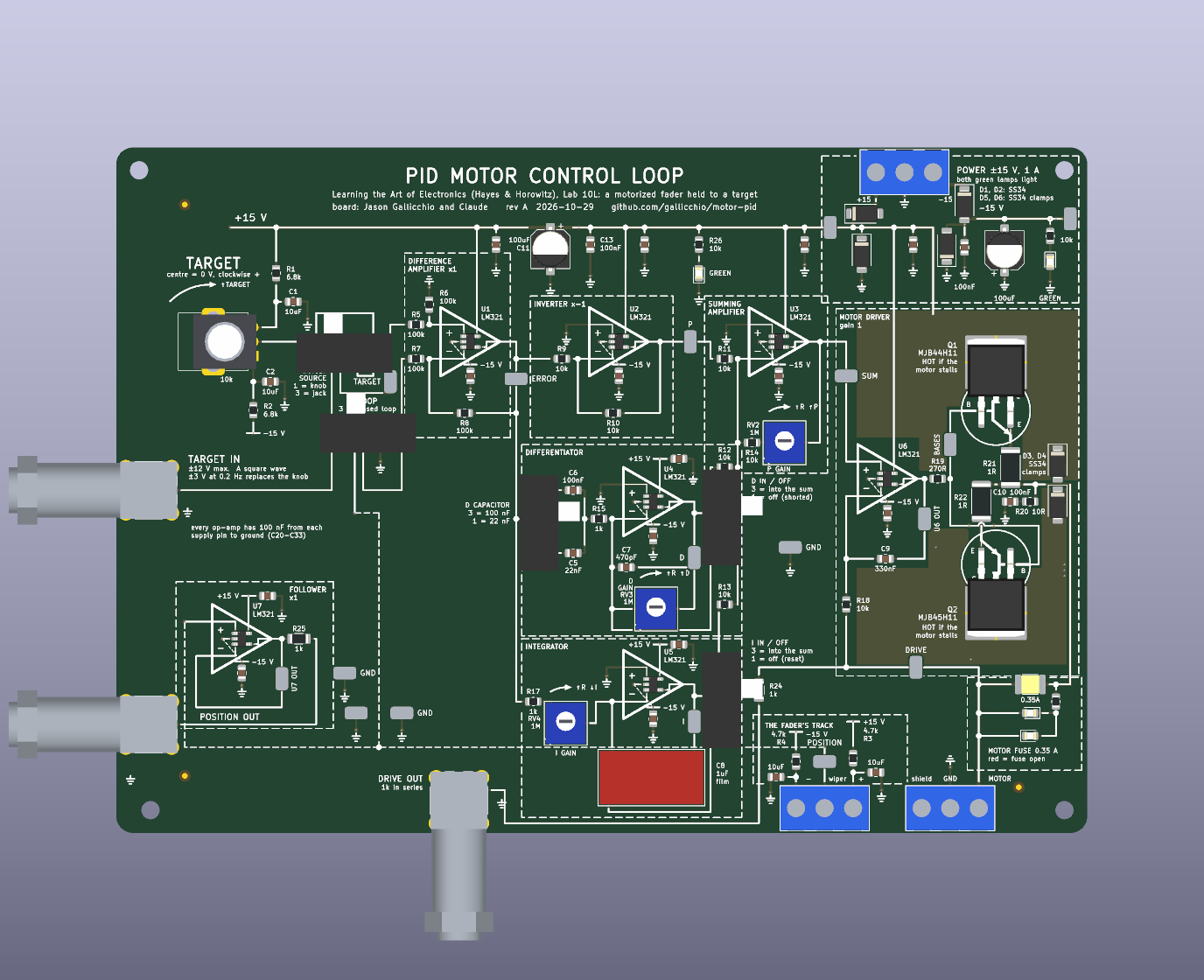
Every node the lab asks you to look at has a probe loop (17 probe loops, four of them ground). Every stage sits in a dashed box named as the book names it. The three gain trimmers are labelled P GAIN, D GAIN and I GAIN, each with an arc over it saying what clockwise does (more resistance: more P, more D, less I); the switches say in words what each position does.
| block | the book | here |
|---|---|---|
| TARGET | a 10k pot between ±15 V through 6.8k | a knob with a centre detent (0 V, clockwise positive), or a BNC jack for a slow square wave; a switch picks |
| pseudo op-amp | unity difference amplifier, inverter, summing amplifier | U1, U2, U3 (LM321) with 100k and 10k as drawn; the summing amplifier's gain is the P GAIN trimmer |
| derivative | C and 1k into an op-amp with 1M feedback, 470 pF across it | U4; a switch picks 22 nF (right for this fader) or the book's 100 nF; D IN / OFF switch |
| integral | 1k + 1M into an op-amp with a capacitor across it | U5 with a 1 µF polypropylene film (its value holds at any voltage); I IN / OFF, where OFF shorts the capacitor so the integrator starts from zero |
| motor driver | op-amp driving a push-pull pair, 10k feedback from the motor side, 0.33 µF from the op-amp's own output, 270 Ω into the bases, 10 Ω + 0.1 µF snubber | U6 with MJB44H11 / MJB45H11 in D2PAK, each in a 2 oz copper pour that is its heatsink, clamp diodes to the rails, a 0.35 A resettable fuse between the push-pull and DRIVE, with red lamps across it: the feedback, the DRIVE loop, DRIVE OUT and the motor are behind it; two more Schottkys clamp a rail left open |
| the plant | the fader's motor and 10k track with 4.7k end resistors (±7.7 V) | two 3-way screw terminals, MOTOR and POT, a POSITION probe loop and a buffered POSITION OUT jack |
| LOOP switch | the book's "break the loop here" | open (POSITION replaced by ground) or closed |
The design departs from the book where the parts or the pedagogy asked for it; each departure is in docs/DESIGN_NOTES.md.
docs/HANDBOOK.md: bring-up without the fader, wiring the fader and checking its polarity, the expected voltage at every loop, and the lab's exercises in the lab's order (P alone and the residual error, raising the gain until it oscillates, adding D, then I, then driving it with a square wave). The back of the board carries the short version.
docs/MANUFACTURING.md is generated by the build: the files to upload, JLCPCB's order form field by field, the cost, and what to look at in their placement preview. There are about $12.21 in parts per board. Order 2 oz outer copper, not the default 1 oz: the copper round the two power transistors is their heatsink.
./make.pyruns, from scripts/parts.py outward: the footprints and 3D stand-ins, the
ngspice simulation of the loop (from the exported netlist, with a model of the
fader), the schematic (scripts/gen_sch.py) and its ERC, 258 circuit
assertions on the netlist (scripts/check_circuit.py), the board
(scripts/layout.py placed and wired by scripts/gen_pcb.py, where every
drawn wire is laid as copper) and its DRC with schematic parity, the fab
package and its checks (scripts/check_outputs.py), and the documents, whose
every quoted number is checked against the build. KiCad 10 is needed; the
build finds its AppImage.
hardware/ — the KiCad project (generated; do not edit by hand)scripts/ — the generators and checkerssim/ — the simulation and its resultsout/motorpid/ — gerbers, BOM, CPL, prints, assembly notesdocs/ — handbook, design notes, manufacturing, imagesCLAUDE_CODE_CHAT.md — how this was designed, prompt by promptHardware under CERN-OHL-P v2 (LICENSE-HARDWARE.txt), scripts under MIT
(LICENSE). The circuit is Hayes & Horowitz's; the board is Jason Gallicchio
and Claude, 2026.
| Qty | Value | Footprint | References |
|---|---|---|---|
| 18 | 100nF | Capacitor_SMD:C_0805_2012Metric | C10, C13, C14, C20, C21, C22, C23, C24, C25, C26, C27, C28, C29, C30, C31, C32 +2 |
| 9 | 10k | Resistor_SMD:R_0805_2012Metric | R9, R10, R11, R12, R13, R14, R18, R26, R27 |
| 7 | LM321 | Package_TO_SOT_SMD:SOT-23-5 | U1, U2, U3, U4, U5, U6, U7 |
| 6 | SS34 | Diode_SMD:D_SMA | D1, D2, D3, D4, D5, D6 |
| 4 | 100k | Resistor_SMD:R_0805_2012Metric | R5, R6, R7, R8 |
| 4 | 10uF | Capacitor_SMD:C_0805_2012Metric | C1, C2, C3, C4 |
| 4 | GND | motorpid:TestPoint_Loop_RH-5019 | TP100, TP101, TP102, TP103 |
| 4 | MountingHole | MountingHole:MountingHole_3.2mm_M3 | MH1, MH2, MH3, MH4 |
| 3 | 1M | motorpid:Potentiometer_Bourns_3362P_Vertical | RV2, RV3, RV4 |
| 3 | 1k | Resistor_SMD:R_0805_2012Metric | R15, R17, R23 |
| 3 | BNC | motorpid:BNC_KYWE_RightAngle | J1, J2, J3 |
| 2 | 100uF | Capacitor_SMD:CP_Elec_6.3x5.4 | C11, C12 |
| 2 | 1R | Resistor_SMD:R_2512_6332Metric | R21, R22 |
| 2 | 1k | Resistor_SMD:R_1206_3216Metric | R24, R25 |
| 2 | 4.7k | Resistor_SMD:R_0805_2012Metric | R3, R4 |
| 2 | 6.8k | Resistor_SMD:R_0805_2012Metric | R1, R2 |
| 2 | GREEN | LED_SMD:LED_0805_2012Metric | LED1, LED2 |
| 2 | RED | LED_SMD:LED_0805_2012Metric | LED3, LED4 |
| 1 | +15 / GND / -15 | motorpid:TerminalBlock_KF301_1x03_P5.00mm | J6 |
| 1 | +15V | motorpid:TestPoint_Loop_RH-5019 | TP9 |
| 1 | -15V | motorpid:TestPoint_Loop_RH-5019 | TP10 |
| 1 | 0.35A | Fuse:Fuse_1812_4532Metric | F1 |
| 1 | 10R | Resistor_SMD:R_0805_2012Metric | R20 |
| 1 | 10k | Potentiometer_THT:Potentiometer_Alps_RK09K_Single_Vertical | RV1 |
| 1 | 1uF | motorpid:C_Film_Panasonic_ECWF_L18.1mm_W9.3mm_P15.00mm | C8 |
| 1 | 22nF | Capacitor_SMD:C_0805_2012Metric | C5 |
| 1 | 270R | Resistor_SMD:R_0805_2012Metric | R19 |
| 1 | 330nF | Capacitor_SMD:C_0805_2012Metric | C9 |
| 1 | 470pF | Capacitor_SMD:C_0805_2012Metric | C7 |
| 1 | BASES | motorpid:TestPoint_Loop_RH-5019 | TP11 |
| 1 | D | motorpid:TestPoint_Loop_RH-5019 | TP4 |
| 1 | D CAPACITOR | motorpid:SW_SPDT_Shouhan_MSK12C02 | SW5 |
| 1 | D IN / OFF | motorpid:SW_SPDT_Shouhan_MSK12C02 | SW3 |
| 1 | DRIVE | motorpid:TestPoint_Loop_RH-5019 | TP7 |
| 1 | ERROR | motorpid:TestPoint_Loop_RH-5019 | TP2 |
| 1 | I | motorpid:TestPoint_Loop_RH-5019 | TP5 |
| 1 | I IN / OFF | motorpid:SW_SPDT_Shouhan_MSK12C02 | SW4 |
| 1 | LOOP | motorpid:SW_SPDT_Shouhan_MSK12C02 | SW2 |
| 1 | MJB44H11 | Package_TO_SOT_SMD:TO-263-2 | Q1 |
| 1 | MJB45H11 | Package_TO_SOT_SMD:TO-263-2 | Q2 |
| 1 | MOTOR + - shield | motorpid:TerminalBlock_KF301_1x03_P5.00mm | J4 |
| 1 | P | motorpid:TestPoint_Loop_RH-5019 | TP3 |
| 1 | POSITION | motorpid:TestPoint_Loop_RH-5019 | TP8 |
| 1 | POT 1 (+) 2 (wiper) 3 (-) | motorpid:TerminalBlock_KF301_1x03_P5.00mm | J5 |
| 1 | SUM | motorpid:TestPoint_Loop_RH-5019 | TP6 |
| 1 | TARGET | motorpid:TestPoint_Loop_RH-5019 | TP1 |
| 1 | TARGET SOURCE | motorpid:SW_SPDT_Shouhan_MSK12C02 | SW1 |
| 1 | U6 OUT | motorpid:TestPoint_Loop_RH-5019 | TP12 |
| 1 | U7 OUT | motorpid:TestPoint_Loop_RH-5019 | TP13 |
gallicchio/op-amp-pcb
The op-amp of Learning the Art of Electronics (Hayes and Horowitz, 2016), Lab 5L, built from six 2N3904 / 2N3906 transistors on a 100 x 100 mm board whose silkscreen is the schematic.

gallicchio/AMOD-and-RFMOD
The tutorial's 2x12 adapter (/mudd/133electronics/icepi-zero-dac-adc/adapterboard/) with a 2 x 6 right-angle Pmod socket on a 15 mm extension of its right-hand end, so an Icepi Zero can drive AMOD-A's and RF-MOD's Pmod…


RSXLX/sunny-the-growing-sunflower-lamp
SUNNY — The Growing Sunflower Lamp | A personal lamp with customizable exteriors, traceable fabrication, and a local creative workspace.

maxlab-io/tokay-lite-pcb
Tokay AI Camera - ESP32 camera development board
It measures 170 × 120 mm and has 2 copper layers, 1.6 mm thick.
110 parts, built around the LM321, CC0805KRX7R9BB104, SS34 and 0805W8F1003T5E (SMT业务专用). The full list of its parts is on this page, with links to each part's symbol and footprint where PCBKit's library has them.
From the gallicchio/motor-pid repository on GitHub, at the commit this page was made from: the board is hardware/motorpid.kicad_pcb and its schematic hardware/motorpid.kicad_sch. PCBKit opens the board in the browser, with nothing to install.
Its repository states no licence, so its author keeps all rights: ask gallicchio before reusing the design.