
2 layers170 × 120 mm
Motor pid
gallicchio/motor-pid
The motor-position feedback loop of Learning the Art of Electronics (Hayes & Horowitz), Lab 10L, as a 170 x 120 mm printed circuit board whose silkscreen is the schematic.
110 parts

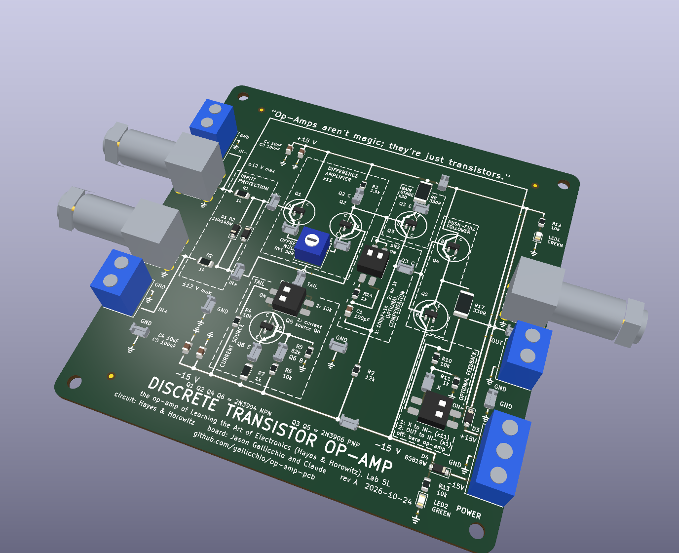
The op-amp of Learning the Art of Electronics (Hayes and Horowitz, 2016), Lab 5L, built from six 2N3904 / 2N3906 transistors on a 100 x 100 mm board whose silkscreen is the schematic.
Opamp is an open-source printed circuit board by gallicchio, from the gallicchio/op-amp-pcb repository on GitHub. It is a 2-layer board of 100 × 100 mm with 65 parts on 26 nets, routed with 188 tracks and 24 vias.
It is built around the MMBT3904, RH-5019 and BNC-KYWE-295-W4-N, with the CC0805KRX7R9BB104, CL21A106KAYNNNE and 1N4148W among its other parts. Its parts include 15 resistors, 7 connectors, 6 diodes, 6 transistors and 5 capacitors.


The op-amp of Learning the Art of Electronics (Hayes and Horowitz, 2016), Lab 5L, built from six 2N3904 / 2N3906 transistors on a 100 x 100 mm board whose silkscreen is the schematic. For a first electronics lab: every node has a loop to hang a scope probe on, three DIP switches select the variants the book walks through, and the inputs, output and power come in on BNCs and screw terminals.
"I want you to build a relatively inexpensive educational Op-Amp PCB out of discrete transistors that I'll order from JLCPCB using only components that they have available and in stock ... The silkscreen should look exactly like the schematic ... The primary goal is clarity, simplicity, educational value, and ease of use for students in their first electronics lab class after having done most of chapter 4 in Learning the Art of Electronics."
Only prompts. The whole project came from a conversation with Claude:
the schematic, the board, the simulation, the fab files and these documents are all
written by the Python under scripts/ and sim/, and nothing was drawn by hand.
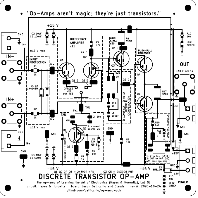
The book's three-stage op-amp, with the book's values:
What the board adds, so a class of first-year students can use it:
Parts cost about $7.79 in parts per board at JLCPCB; the fixed assembly fees make the first board about $70 and each further one about $9, so about $15 each for 10 assembled boards. See docs/MANUFACTURING.md.
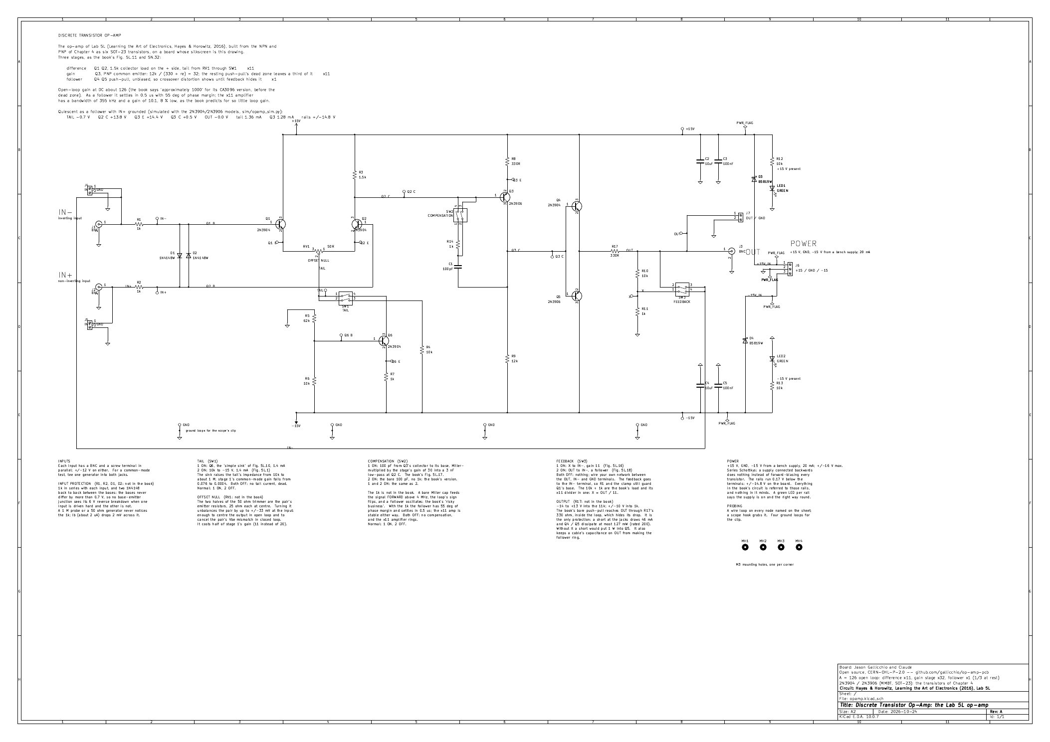
docs/HANDBOOK.md is the student and instructor guide: how to power it, what every switch and loop does, the quiescent voltage at every loop, the bring-up order for a new board, and a set of exercises that follow Lab 5L stage by stage. The back of the board carries the short version.
Needs KiCad 10 (an AppImage is enough), Python 3 with Pillow, pdftoppm
(poppler-utils) for the images and, optionally, libngspice for the simulation.
git clone https://github.com/gallicchio/op-amp-pcb.git
cd op-amp-pcb
export KICAD_APPIMAGE=$HOME/.local/bin/kicad-10.0.7-x86_64.AppImage   # or kicad-cli on PATH
./make.py              # footprints, models, simulation, schematic, board, checks, fab files, docs
./make.py --clean      # delete everything it generates
The build stops on any ERC or DRC violation, on any of the 110 circuit assertions that read the exported netlist back against the book's circuit, on a schematic text overlap, on a fab-package problem (an order code whose JLCPCB description no longer matches, a QR code that does not decode from the board file) and on any number in these documents that no longer matches the build.
make.py                one command builds and checks everything
scripts/parts.py       every part: value, footprint, LCSC code, stock, JLCPCB rotation
scripts/layout.py      the board: placements, the silkscreen wires, texts and boxes
scripts/gen_sch.py     writes hardware/opamp.kicad_sch
scripts/gen_pcb.py     writes hardware/opamp.kicad_pcb (copper follows the silk wires)
scripts/check_*.py     the netlist, the schematic sheet and the fab package
sim/opamp_sim.py       ngspice: operating point, loop gain, step response, swing, null
out/opamp/             gerbers, BOM, CPL (native and JLCPCB), prints, PLACEMENT_CHECKS
docs/ MANUFACTURING, HANDBOOK, DESIGN_NOTES, imagesCircuit: Hayes and Horowitz. Board: Jason Gallicchio and Claude. Hardware under CERN-OHL-P-2.0, scripts under MIT; see LICENSE.
| Qty | Value | Footprint | References |
|---|---|---|---|
| 5 | 10k | Resistor_SMD:R_0805_2012Metric | R4, R6, R10, R12, R13 |
| 4 | 2N3904 | Package_TO_SOT_SMD:SOT-23 | Q1, Q2, Q4, Q6 |
| 4 | GND | opamp:TestPoint_Loop_RH-5019 | TP100, TP101, TP102, TP103 |
| 4 | MountingHole | MountingHole:MountingHole_3.2mm_M3 | MH1, MH2, MH3, MH4 |
| 3 | 1k | Resistor_SMD:R_1206_3216Metric | R1, R2, R7 |
| 3 | BNC | opamp:BNC_KYWE_RightAngle | J1, J2, J3 |
| 2 | 100nF | Capacitor_SMD:C_0805_2012Metric | C3, C5 |
| 2 | 10uF | Capacitor_SMD:C_0805_2012Metric | C2, C4 |
| 2 | 1N4148W | Diode_SMD:D_SOD-123 | D1, D2 |
| 2 | 1k | Resistor_SMD:R_0805_2012Metric | R11, R14 |
| 2 | 2N3906 | Package_TO_SOT_SMD:SOT-23 | Q3, Q5 |
| 2 | 330R | Resistor_SMD:R_2512_6332Metric | R8, R17 |
| 2 | B5819W | Diode_SMD:D_SOD-123 | D3, D4 |
| 2 | GREEN | LED_SMD:LED_0805_2012Metric | LED1, LED2 |
| 1 | +15 / GND / -15 | opamp:TerminalBlock_KF301_1x03_P5.00mm | J6 |
| 1 | +15V | opamp:TestPoint_Loop_RH-5019 | TP11 |
| 1 | -15V | opamp:TestPoint_Loop_RH-5019 | TP12 |
| 1 | 1.5k | Resistor_SMD:R_0805_2012Metric | R3 |
| 1 | 100pF | Capacitor_SMD:C_0805_2012Metric | C1 |
| 1 | 12k | Resistor_SMD:R_0805_2012Metric | R9 |
| 1 | 50R | opamp:Potentiometer_Bourns_3362P_Vertical | RV1 |
| 1 | 62k | Resistor_SMD:R_0805_2012Metric | R5 |
| 1 | COMPENSATION | opamp:SW_DIP_SPSTx02_KingTek_DSIC02_P2.54mm | SW2 |
| 1 | FEEDBACK | opamp:SW_DIP_SPSTx02_KingTek_DSIC02_P2.54mm | SW3 |
| 1 | IN+ | opamp:TestPoint_Loop_RH-5019 | TP2 |
| 1 | IN+ / GND | opamp:TerminalBlock_KF301_1x02_P5.00mm | J5 |
| 1 | IN- | opamp:TestPoint_Loop_RH-5019 | TP1 |
| 1 | IN- / GND | opamp:TerminalBlock_KF301_1x02_P5.00mm | J4 |
| 1 | OUT | opamp:TestPoint_Loop_RH-5019 | TP9 |
| 1 | OUT / GND | opamp:TerminalBlock_KF301_1x02_P5.00mm | J7 |
| 1 | Q1 E | opamp:TestPoint_Loop_RH-5019 | TP13 |
| 1 | Q2 C | opamp:TestPoint_Loop_RH-5019 | TP6 |
| 1 | Q2 E | opamp:TestPoint_Loop_RH-5019 | TP14 |
| 1 | Q3 C | opamp:TestPoint_Loop_RH-5019 | TP8 |
| 1 | Q3 E | opamp:TestPoint_Loop_RH-5019 | TP7 |
| 1 | Q6 B | opamp:TestPoint_Loop_RH-5019 | TP5 |
| 1 | Q6 E | opamp:TestPoint_Loop_RH-5019 | TP4 |
| 1 | TAIL | opamp:SW_DIP_SPSTx02_KingTek_DSIC02_P2.54mm | SW1 |
| 1 | TAIL | opamp:TestPoint_Loop_RH-5019 | TP3 |
| 1 | X | opamp:TestPoint_Loop_RH-5019 | TP10 |
gallicchio/motor-pid
The motor-position feedback loop of Learning the Art of Electronics (Hayes & Horowitz), Lab 10L, as a 170 x 120 mm printed circuit board whose silkscreen is the schematic.

gallicchio/AMOD-and-RFMOD
The tutorial's 2x12 adapter (/mudd/133electronics/icepi-zero-dac-adc/adapterboard/) with a 2 x 6 right-angle Pmod socket on a 15 mm extension of its right-hand end, so an Icepi Zero can drive AMOD-A's and RF-MOD's Pmod…

leedanie2/curve-tracer
Programmable semiconductor curve tracer: STM32 firmware, two-layer KiCad PCB, SPICE Monte Carlo analysis, and a host-side SPICE-parameter extraction pipeline. Hardware in bring-up.

RSXLX/sunny-the-growing-sunflower-lamp
SUNNY — The Growing Sunflower Lamp | A personal lamp with customizable exteriors, traceable fabrication, and a local creative workspace.


TIGP-Experimental-Methods/class-board-2026
TIGP class instrument 2026: one board, five blocks - KiCad hardware, ESP32-S3 firmware, phone PWA, Python API, workbook

Simplycissmus/windowmaster-s3-controller
Open hardware and ESP32-S3 firmware for a local 24 V window actuator controller with MQTT and Home Assistant integration.
It measures 100 × 100 mm and has 2 copper layers, 1.6 mm thick.
65 parts, built around the MMBT3904, RH-5019, BNC-KYWE-295-W4-N and CC0805KRX7R9BB104. The full list of its parts is on this page, with links to each part's symbol and footprint where PCBKit's library has them.
From the gallicchio/op-amp-pcb repository on GitHub, at the commit this page was made from: the board is hardware/opamp.kicad_pcb and its schematic hardware/opamp.kicad_sch. PCBKit opens the board in the browser, with nothing to install.
Its repository states no licence, so its author keeps all rights: ask gallicchio before reusing the design.