Skip to the content
PCBKitNew board
4 layers62 × 51 mmCANTranslate, the printed circuit board in 3D

The hardware design for CANTranslate facilitates physical interfacing and electrical translation between multiple CAN bus systems.

Size
62 × 51 mm
Copper layers
4
Thickness
1.61 mm
Parts
48
Nets
84
Pads
213
Tracks, vias
296, 170
Pours
3
Routed
Yes
KiCad
KiCad 9.0 (file 20241229)
Created
4 May 2025
Updated
2 Nov 2025

Overview

CANTranslate is an open-source printed circuit board by fwillard, from the fwillard/CANTranslate repository on GitHub. It is a 4-layer board of 62 × 51 mm with 48 parts on 84 nets, routed with 296 tracks and 170 vias.

It is built around the STM32F205RGT6, SN65HVD230D and AMS1117-3.3, with the TPS2116DRL, USBLC6-2SC6 and SM04B-GHS-TB(LF)(SN) among its other parts. Its parts include 15 capacitors, 10 resistors, 6 ICs, 4 connectors and 4 switches. It belongs with the STM32 boards of this library.

Main components

6

README

Hardware/KiCad/CANTranslate/README.md

CANTranslate – Hardware Design

Overview

The hardware design for CANTranslate facilitates physical interfacing and electrical translation between multiple CAN bus systems. This includes power management, bus isolation, transceivers, and microcontroller integration for reliable embedded CAN communication.
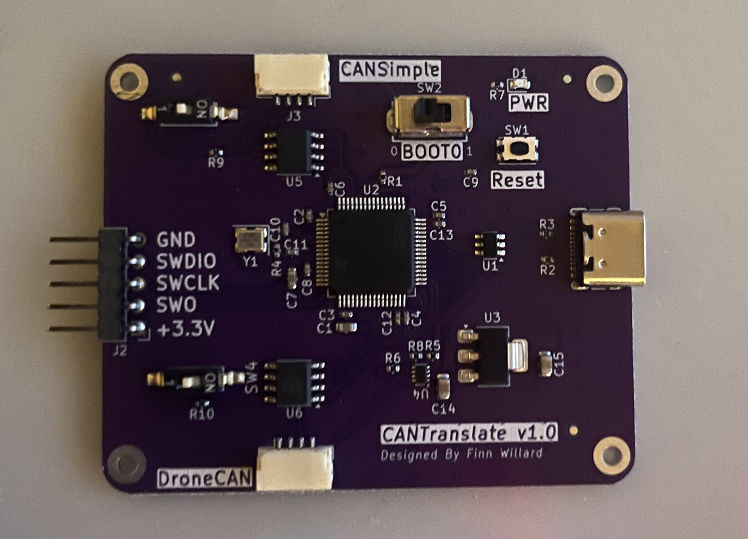
board

Features

  • Dual SN65HVD230 CAN transceivers (CAN 2.0)
  • STM32F205RGT6 microcontroller
  • Power input via USB or 5V pin on the CAN header
  • Power source selection using TPS2116DRL (USB VBUS prioritized)
  • Debug interface (SWD)

Hardware Design Files

The following files are included in the /Hardware/KiCad/CANTranslate directory:

  • CANTranslate.kicad_pro
  • CANTranslate.kicad_sch – Schematic file
  • CANTranslate.kicad_pcb – PCB layout
  • CustomParts.kicad_sym – Custom symbol library
  • KMR223G LFG.STEP – 3D model of tactile switch
  • fabrication-toolkit-options.json – Fabrication preferences
  • fp-lib-table – Footprint library table
  • sym-lib-table – Symbol library table

Power Requirements

  • Power Inputs:

    • 5V from USB VBUS (primary source, with ESD protection)

    • 5V from the CAN header power pin (secondary source, no ESD protection)

  • Power Selection:

    • The board uses a TPS2116DRL power multiplexer to automatically select the power source. When both USB and CAN header power are connected, the TPS2116DRL prioritizes USB VBUS, ensuring safe and seamless switching without back-feeding either source.
  • Voltage Regulation:

    • The selected 5V supply is regulated down to 3.3V using an AMS1117-3.3 linear voltage regulator, providing stable power for the STM32F205RGT6 MCU and the SN65HVD230 CAN transceivers.
  • Protection Features:

    • The USB power input includes ESD protection to safeguard against electrostatic discharge events.

Toolchain

  • EDA Software: KiCad 9.x

Licensing

Hardware design files are released under the CERN Open Hardware License v2 - Permissive

Parts

48
QtyValueFootprintReferences
7100nCapacitor_SMD:C_0402_1005MetricC2, C3, C4, C5, C6, C8, C9
4MountingHole_PadMountingHole:MountingHole_2.2mm_M2_PadH1, H2, H3, H4
310kResistor_SMD:R_0402_1005MetricR1, R6, R8
3120Resistor_SMD:R_0402_1005MetricR7, R9, R10
3FiducialFiducial:Fiducial_1mm_Mask2mmFID1, FID2, FID3
210pCapacitor_SMD:C_0402_1005MetricC10, C11
222uCapacitor_SMD:C_0805_2012MetricC14, C15
22u2Capacitor_SMD:C_0402_1005MetricC12, C13
25k1Resistor_SMD:R_0402_1005MetricR2, R3
2SM04B-GHS-TB(LF)(SN)Connector_JST:JST_GH_SM04B-GHS-TB_1x04-1MP_P1.25mm_HorizontalJ3, J4
2SN65HVD230Package_SO:SOIC-8_3.9x4.9mm_P1.27mmU5, U6
2SW_SPSTDSIC01LSGET:SW-SMD_DSIC01LSGETSW3, SW4
110uCapacitor_SMD:C_0603_1608MetricC1
116MHzCrystal:Crystal_SMD_3225-4Pin_3.2x2.5mmY1
11uCapacitor_SMD:C_0603_1608MetricC7
136kResistor_SMD:R_0402_1005MetricR5
1470Resistor_SMD:R_0402_1005MetricR4
1AMS1117-3.3Package_TO_SOT_SMD:SOT-223-3_TabPin2U3
1Conn_01x05_PinConnector_PinHeader_2.54mm:PinHeader_1x05_P2.54mm_HorizontalJ2
1REDLED_SMD:LED_0603_1608MetricD1
1STM32F205RGT6Package_QFP:LQFP-64_10x10mm_P0.5mmU2
1SW_PushButton_Switch_SMD:SW_Push_1P1T_NO_CK_KMR2SW1
1SW_SPDTeasyeda2kicad:SW-TH_SS12D07VG4SW2
1TPS2116DRLPackage_TO_SOT_SMD:SOT-583-8U4
1USBLC6-2SC6Package_TO_SOT_SMD:SOT-23-6U1
1USB_C_Receptacle_USB2.0_16PConnector_USB:USB_C_Receptacle_GCT_USB4105-xx-A_16P_TopMnt_HorizontalJ1

Questions

How big is the CANTranslate PCB?

It measures 62 × 51 mm and has 4 copper layers, 1.61 mm thick.

What parts does the CANTranslate use?

48 parts, built around the STM32F205RGT6, SN65HVD230D, AMS1117-3.3 and TPS2116DRL. The full list of its parts is on this page, with links to each part's symbol and footprint where PCBKit's library has them.

Where can I download the CANTranslate KiCad files?

From the fwillard/CANTranslate repository on GitHub, at the commit this page was made from: the board is Hardware/KiCad/CANTranslate/CANTranslate.kicad_pcb and its schematic Hardware/KiCad/CANTranslate/CANTranslate.kicad_sch. PCBKit opens the board in the browser, with nothing to install.

Can I use the CANTranslate design in my own project?

Its repository states no licence, so its author keeps all rights: ask fwillard before reusing the design.

Similar boards

  • 4 layers58.7 × 35.5 mmMeowCU, the printed circuit board in 3D

    MeowCU

    eggsacc/pcb-MeowCU

    4-layer STM32F405RGT6 MeowCU 🐱 (MCU) dev module with commonly used peripherals broken out for easy access, and a dedicated CAN transceiver. Also includes 2 user programmable buttons and mini OLED display.

    69 parts
  • 4 layers101 × 75 mmSdm24logger, the printed circuit board in 3D

    Sdm24logger

    sundevilmotorsports/pcb-dev

    PCB development repository

    120 parts3
  • 2 layers133 × 123 mmMissionOrderFile, the printed circuit board in 3D

    MissionOrderFile

    wasa-rockoon/WOBC

    WASAロケットプロジェクト 共通電装基盤

    534 parts1MIT
  • 2 layers90 × 90 mmPocketPSU elec main, the printed circuit board in 3D

    PocketPSU elec main

    jarrod89/pocketPSU

    Input1: - Output1 can be used to supply pocketPSU via a battery - Optional battery charging capability (addon board with BMS)

    97 parts2
  • 4 layers97.7 × 58.5 mmSumobot pcb, the printed circuit board in 3D

    Sumobot pcb

    keer-nova74/STM32-Sumo-Robot-Controller-PCB

    A robotics controller PCB project using an STM32 microcontroller, dual motor drivers, sensor interfaces, and power management, designed using KiCad.

    111 parts
  • 4 layers76.5 × 54.1 mmUNFINISHEDInvictusDES V2, the printed circuit board in 3D

    UNFINISHEDInvictusDES V2

    taisai4u/invictus

    A flight computer that provides complete attitude determination for rockets.

    76 parts
  • 4 layers40 × 31.3 mmDps satelite, the printed circuit board in 3D

    Dps satelite

    UbiTrich/home-assistant-poe-satellite

    ESP32-S3 PoE voice satellite for Home Assistant

    100 parts
  • 4 layers84.5 × 60 mmBldc driver, the printed circuit board in 3D

    Bldc driver

    koson/spel-bldc-esc

    Open-source BLDC motor electronic speed controller (yet another)

    100 parts4