2 layers90 × 40 mm
 fullyautomated/tinypol11
48-V Input Affordable 1.2-A Output Point-of-Load DC/DC Converter
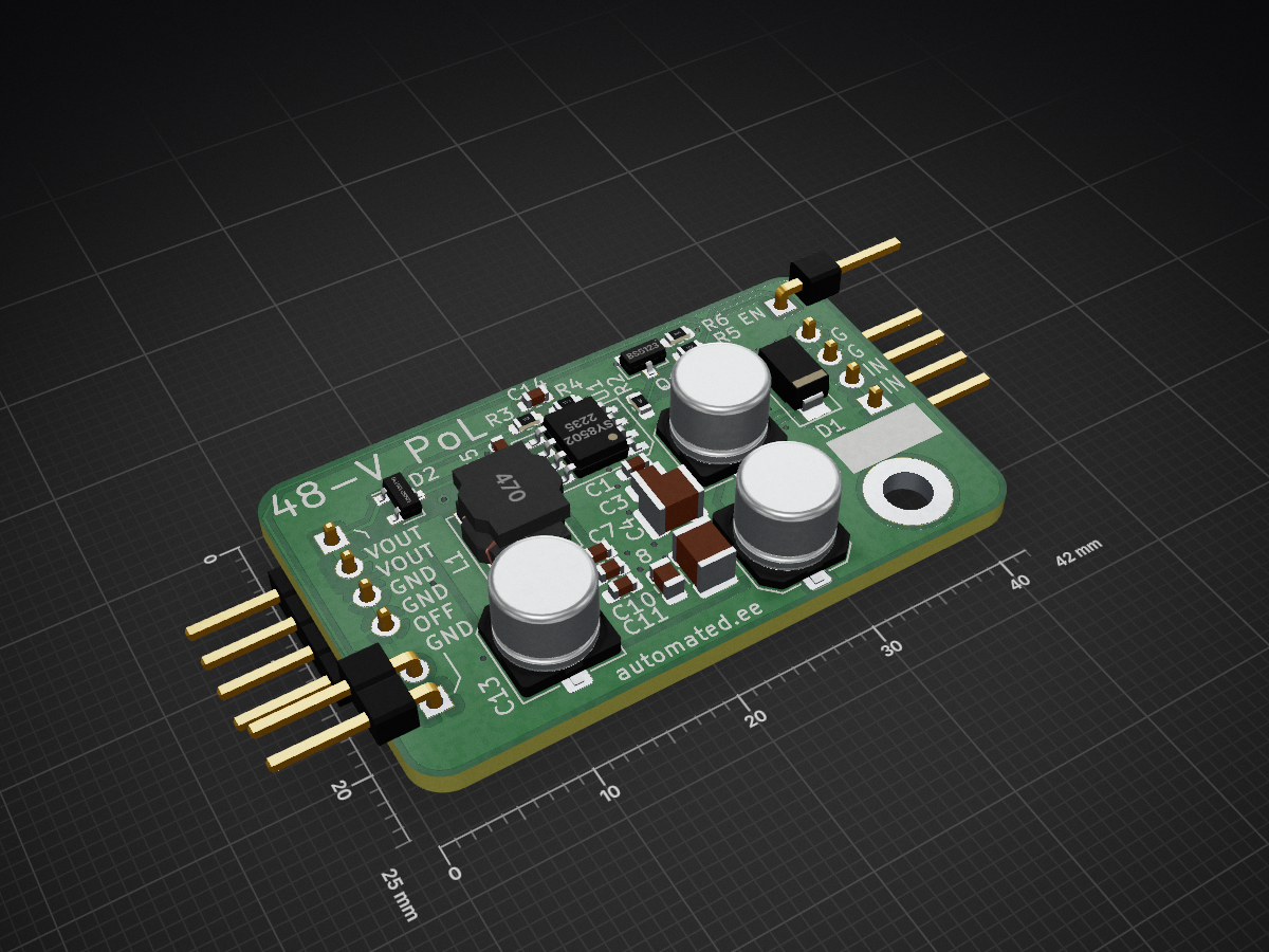
Tinypol is an open-source printed circuit board by fullyautomated, from the fullyautomated/tinypol repository on GitHub. It is a 2-layer board of 42 × 25 mm with 31 parts on 11 nets, routed with 76 tracks and 30 vias.
It is built around the SY8502FCC and BSS123. Its parts include 14 capacitors, 6 resistors, 4 connectors, 2 diodes and 1 IC. It belongs with the power boards of this library.

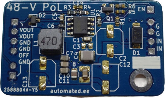
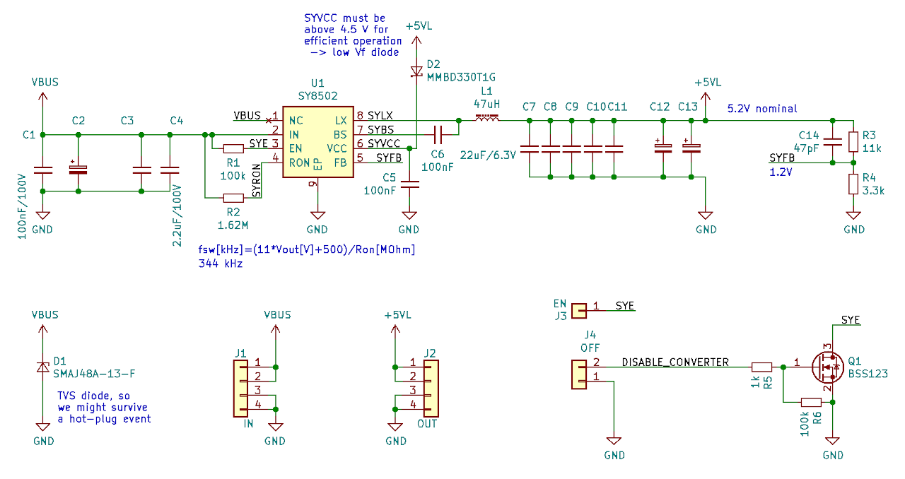
This design is based around the Silergy SY8502FCC converter.
IC Datasheet. Board Schematic.
For layout, see the .kicad_pcb file in the repository.
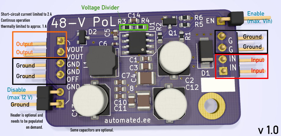
Connect the input side to the power source, and the output side to the load. The converter powers on automatically above approx. 6.2V input. Output is programmed to 5.2 volt, can be changed by replacing R3 and/or R4. Reference voltage is 1.2 V. Supported input voltage is around 56-V, above which the D1 TVS diode will start to clamp. You can remove this to increase maximum input voltage to 85V abs max, but then you should avoid hot-plugging the board.
There are two ways to shut down the converter while input power is present.
Alternatively, you can disconnect the input.
| Specifications | |
|---|---|
| Dimensions: | 25x42x6mm (without pin headers) |
| Mass: | 4.8g (without pin headers) |
| Mounting Hole: | M3 at (-6;-4)mm from bottom right corner |
| Input Voltage: | 6.8V - 56V |
| Output Voltage: | 5.2V (default) Optionally between 1.8V and 24V |
| Internal Reference Voltage: | 1.2V |
| Output Ripple: | 500mVpp with no load 80mVpp in Continuous Conduction Mode |
| Output Current: | 1.8A peak 1.2A continuous |
| Power Stage: | Synchronous buck with 500mOhm (HS) and 240mOhm (LS) nMOS switches |
| Overtemperature Protection: | Yes, at 150 degrees Celsius |
| Short Circuit Protection: | Yes, at 2A |
| Fixed Switching Frequency: | No. In Continuous Conduction Mode fSW is approx. 340 kHz |
| Soft Start: | 2ms, fixed in silicon |
| Transient Input Overvoltage Protection: | Yes, with on-board TVS diode |
| Output Overvoltage Protection: | No. |
| Hot-Plug Capable: | Yes. |
| Soft Shutdown: | Yes (logic high on OFF pin) or Yes (pulling EN pin low) |
| Output ON Indicator: | No. |
| Power Good Output: | No. |
| RoHS: | Yes, plus tantalum-free. |
The IC looks quite OK! Output has little noise (thanks to the plentiful output MLCCs) but high ripple because of low switching frequency and hysteretic operation. Rectifier MOSFET control looks good. Short circuit test looks good. Startup after short is good.
The SYE (enable) pin does not seem to be properly deglitched internally. I can make it behave erronously by feeding noise into EN. The on-board 100k pullup is strong enough to counteract spurious noise, but you can drive it externally to make it do weird things.
I can tickle the IC to make the output oscillate, but it settles rather quickly. Would not use it to power sensitive circuits directly, without a second regulator.
Driving it close to 2 A output makes it run very hot. The thermal pad below the IC seems to be well soldered and the board is sinking the heat. Inductor heats up quite a bit; a better one would probably help increase efficiency, but it is okay for its typical use case, and you would not get much more current out of this anyway. The board has nice thermal mass!
Tried adding 2200uF electrolytic cap to the output, this did not reduce ripple (because it is determined by the hysteresis of the comparator) but pushed the switching frequency down to the audible range with low load.
One weirdness I observed: when running it with a hard short at its output the output current is initially clamped at 2A, at which the converter heates up, which changes the overcurrent comparator's threshold. After thermal shutdown kicked in, I let the IC cool down, and repeated the test. Now the output current into a short was only 1A. This did not change after power cycling the IC, and seems to be permanent. I will repeat this test on different boards too, but I want to set up a test script first so I can compare chips before-after, and that needs more work on our lab instrumentation.
Either way, this IC looks very usable, while being much cheaper than any of its alternatives.
| Qty | Value | Footprint | References |
|---|---|---|---|
| 3 | 22uF/6.3V | Capacitor_SMD:C_0603_1608Metric | C7, C8, C9 |
| 3 | d.n.p. | Capacitor_SMD:C_Elec_6.3x5.8 | C2, C12, C13 |
| 2 | 100k | Resistor_SMD:R_0603_1608Metric | R1, R6 |
| 1 | 1.62M | Resistor_SMD:R_0603_1608Metric | R2 |
| 1 | 100nF | Capacitor_SMD:C_0402_1005Metric | C6 |
| 1 | 100nF | Capacitor_SMD:C_0603_1608Metric | C5 |
| 1 | 100nF/100V | Capacitor_SMD:C_0603_1608Metric | C1 |
| 1 | 11k | Resistor_SMD:R_0603_1608Metric | R3 |
| 1 | 1k | Resistor_SMD:R_0603_1608Metric | R5 |
| 1 | 2.2uF/100V | Capacitor_SMD:C_0805_2012Metric | C3 |
| 1 | 2.2uF/100V | Capacitor_SMD:C_1210_3225Metric | C4 |
| 1 | 22uF/6.3V | Capacitor_SMD:C_0805_2012Metric | C10 |
| 1 | 22uF/6.3V | Capacitor_SMD:C_1210_3225Metric | C11 |
| 1 | 3.3k | Resistor_SMD:R_0603_1608Metric | R4 |
| 1 | 47pF | Capacitor_SMD:C_0603_1608Metric | C14 |
| 1 | 47uH | Inductor_SMD:L_Bourns_SRN6045TA | L1 |
| 1 | BSS123 | Package_TO_SOT_SMD:SOT-23 | Q1 |
| 1 | EN | Connector_PinHeader_2.54mm:PinHeader_1x01_P2.54mm_Horizontal | J3 |
| 1 | Fully_Automated_Logo | Automated:falogo_small_copper | G1 |
| 1 | IN | Connector_PinHeader_2.54mm:PinHeader_1x04_P2.54mm_Horizontal | J1 |
| 1 | M3 | MountingHole:MountingHole_3.2mm_M3_ISO7380_Pad | H1 |
| 1 | MMBD330T1G | Diode_SMD:D_SOT-23_ANK | D2 |
| 1 | OFF | Connector_PinHeader_2.54mm:PinHeader_1x02_P2.54mm_Horizontal | J4 |
| 1 | OUT | Connector_PinHeader_2.54mm:PinHeader_1x04_P2.54mm_Horizontal | J2 |
| 1 | SMAJ48A-13-F | Diode_SMD:D_SMA | D1 |
| 1 | SY8502 | Automated:SO8E_Silergy_4x5mm_EP3.4x2.55mm | U1 |
It measures 42 × 25 mm and has 2 copper layers, 1.6 mm thick.
31 parts, built around the SY8502FCC and BSS123. The full list of its parts is on this page, with links to each part's symbol and footprint where PCBKit's library has them.
From the fullyautomated/tinypol repository on GitHub, at the commit this page was made from: the board is tinypol.kicad_pcb. PCBKit opens the board in the browser, with nothing to install.
Its repository states no licence, so its author keeps all rights: ask fullyautomated before reusing the design.

Teslafly/Moxie_drive
A motor drive based off https://github.com/vedderb/bldc-hardware capable of 75v and 100a continuous for silly electric vehicles

HacklabJKL/sergei_cnc2
Second version of Hacklab's custom built CNC machine

antmicro/kria-k26-devboard
Open source AMD Xilinx Kria UltraScale+ SoM baseboard

anthony-bernaert/ftdi-jtag-programmer
FTDI-based JTAG Programmer Circuit for FPGAs

RichardRozehnal/Gotek-Floppy-Disk-Emulator-V2
Floppy disk emulator for old computers and machines, Amiga, Atari ST, etc.

antmicro/lpddr4-test-board
Experimental development board interfacing Xilinx Kintex-7 FPGA with LPDDR4 SDRAM

tdjastrzebski/All-Purpose-Power-Micro-Controller
General purpose power controller, capable of driving soldering irons using different voltages and probe types.