2 layers

 friedrich/soil-moisture-sensor7
Capacitive moisture sensor
Moisture sensor is an open-source printed circuit board by friedrich, from the friedrich/soil-moisture-sensor repository on GitHub. It is a 2-layer board of 40 × 125 mm with 35 parts on 33 nets, routed with 281 tracks and 86 vias.
It is built around the ESP32-C3-WROOM-02-N4, TPS631000DRL and RC0805FR-0710KL, with the GRM21BR71A106KA73, GRM21A5C2E180JW01 and GRM21BR61A476ME15L among its other parts. Its parts include 14 resistors, 8 capacitors, 3 ICs, 3 diodes and 1 connector. It belongs with the sensors and measurement boards and the ESP32 and RISC-V boards of this library.


A capacitive moisture sensor board employing an ESP32-C3 RISC-V microcontroller capable of transmitting measurements via Wi-Fi and Bluetooth 5 (LE). The board is powered by a single cell LiPo battery, which can be charged using the USB-C port.
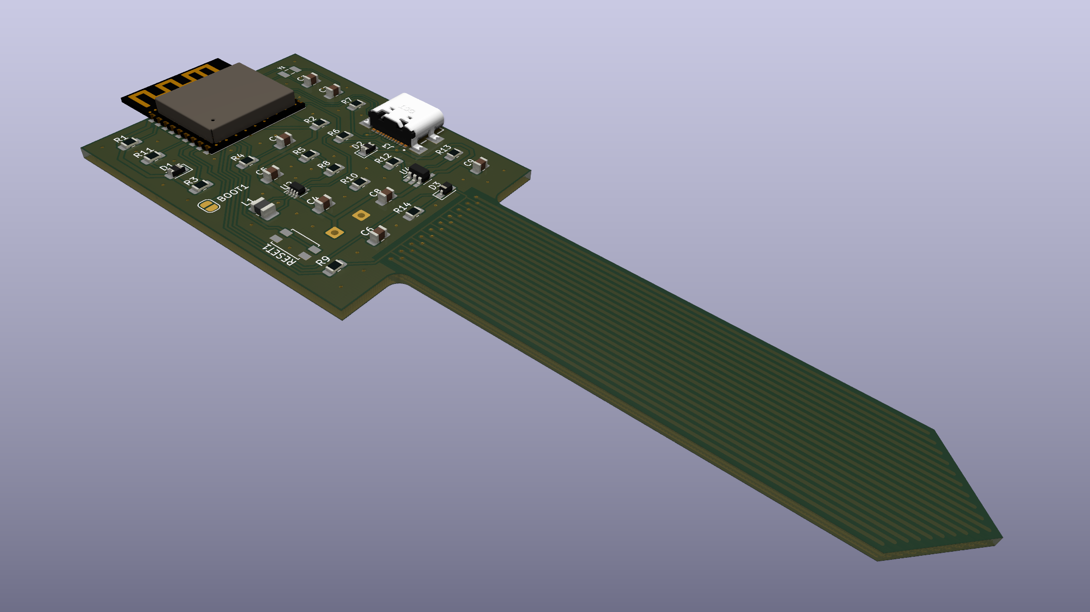
Components are spaced quite far apart, with the goal of making it easier to solder them by hand.
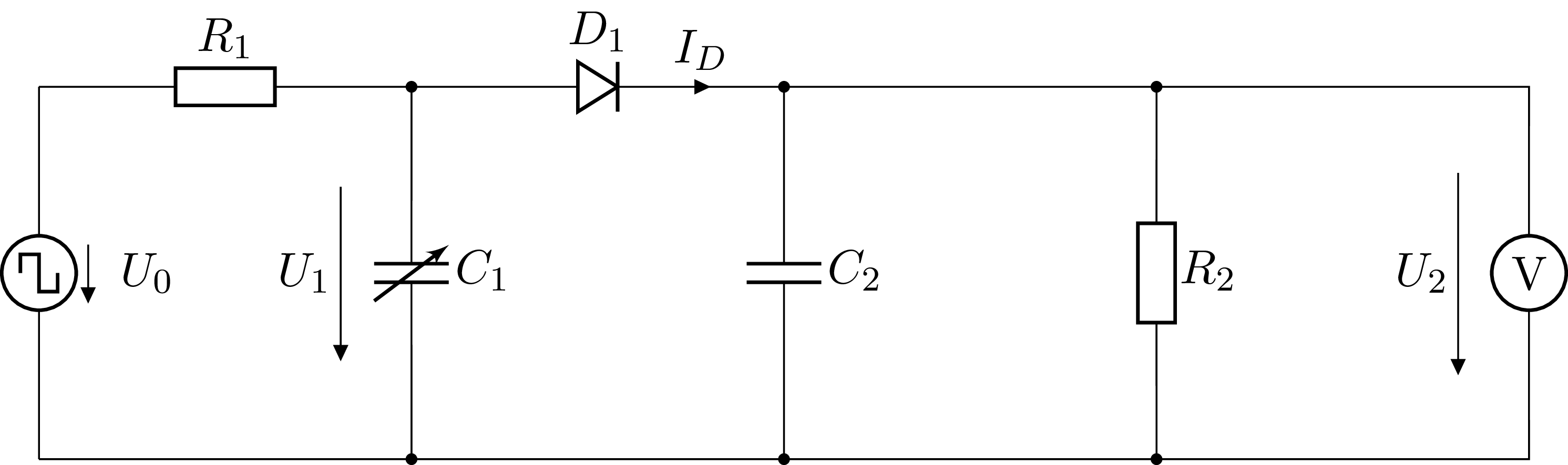
The sensor circuit consists of the following building blocks:
Since resistor $R_2$ is chosen to be quite large, the impact of the peak voltage detector on the low pass filter becomes negligible, as soon as $C_2$ reaches a stable voltage. Just considering the voltage source together with the low pass filter leads to a peak voltage of
$$ U_p = U_+ \frac{1 - e^{-\omega T D}}{1 - e^{-\omega T}}, $$
where $U_+$ is the high voltage of the voltage source, $T$ the period, $D$ the duty cycle, and $\omega = 1/(R_1 C_2)$. The peak voltage has a range from $U_+$ for zero $C_2$ down to $D U_+$ for infinite $C_2$.
| Qty | Value | Footprint | References |
|---|---|---|---|
| 4 | 10k | Resistor_SMD:R_0805_2012Metric_Pad1.20x1.40mm_HandSolder | R1, R2, R3, R10 |
| 2 | 10uF | Capacitor_SMD:C_0805_2012Metric_Pad1.18x1.45mm_HandSolder | C8, C9 |
| 2 | 18pF | Capacitor_SMD:C_0805_2012Metric_Pad1.18x1.45mm_HandSolder | C2, C3 |
| 2 | 1k | Resistor_SMD:R_0805_2012Metric_Pad1.20x1.40mm_HandSolder | R4, R9 |
| 2 | 47uF | Capacitor_SMD:C_0805_2012Metric_Pad1.18x1.45mm_HandSolder | C4, C5 |
| 2 | 5.1k | Resistor_SMD:R_0805_2012Metric_Pad1.20x1.40mm_HandSolder | R6, R7 |
| 2 | Conn_01x01 | Connector_Wire:SolderWire-0.25sqmm_1x01_D0.65mm_OD1.7mm | -BATT1, +BATT1 |
| 2 | LED | Diode_SMD:D_0805_2012Metric_Pad1.15x1.40mm_HandSolder | D1, D2 |
| 1 | 1M | Resistor_SMD:R_0805_2012Metric_Pad1.20x1.40mm_HandSolder | R14 |
| 1 | 1nF | Capacitor_SMD:C_0805_2012Metric_Pad1.18x1.45mm_HandSolder | C6 |
| 1 | 1uF | Capacitor_SMD:C_0805_2012Metric_Pad1.18x1.45mm_HandSolder | C1 |
| 1 | 1uH | Inductor_SMD:L_1008_2520Metric_Pad1.43x2.20mm_HandSolder | L1 |
| 1 | 220R | Resistor_SMD:R_0805_2012Metric_Pad1.20x1.40mm_HandSolder | R12 |
| 1 | 3.3k | Resistor_SMD:R_0805_2012Metric_Pad1.20x1.40mm_HandSolder | R13 |
| 1 | 32.768kHz | Crystal:Crystal_SMD_G8-2Pin_3.2x1.5mm_HandSoldering | Y1 |
| 1 | 47R | Resistor_SMD:R_0805_2012Metric_Pad1.20x1.40mm_HandSolder | R11 |
| 1 | 511k | Resistor_SMD:R_0805_2012Metric_Pad1.20x1.40mm_HandSolder | R5 |
| 1 | 91k | Resistor_SMD:R_0805_2012Metric_Pad1.20x1.40mm_HandSolder | R8 |
| 1 | D | Diode_SMD:D_SOD-323_HandSoldering | D3 |
| 1 | ESP32-C3-WROOM-02 | library:ESP32-C3-WROOM-02 | U1 |
| 1 | EVQ-Q2F03W | Button_Switch_SMD:SW_SPST_EVQP2 | RESET1 |
| 1 | Jumper_2_Open | Jumper:SolderJumper-2_P1.3mm_Open_RoundedPad1.0x1.5mm | BOOT1 |
| 1 | MCP73832 | Package_TO_SOT_SMD:SOT-23-5_HandSoldering | U4 |
| 1 | TPS631000 | Package_TO_SOT_SMD:SC-70-8 | U2 |
| 1 | USB4110 | library:USB4110-GF-A_REVB | J3 |

daedalus-ind/icarus-hardware
Hardware of the onboard flight computer for the Icarus rocket.


RV-crtl/Digital-Hearing-Aid-G1
Anna — controls · Ryan — BT/telecoil · Mariya — microphone/DSP · Naomi — speaker output · Interface contracts


VikingMotorsports/Battery-Management-System-Capstone-2026
The BMS Capstones deliverables

ECE49022Team22/delivery-robot-pcb
Delivery robot KiCad PCB project and reusable 3.3 V LDO module

kekoraa/usb-c-pd-bench-breakout
USB-C PD trigger/breakout with selectable voltage requests and a routed two-layer KiCad PCB. Design-stage
It measures 40 × 125 mm and has 2 copper layers, 1.6 mm thick.
35 parts, built around the ESP32-C3-WROOM-02-N4, TPS631000DRL, RC0805FR-0710KL and GRM21BR71A106KA73. The full list of its parts is on this page, with links to each part's symbol and footprint where PCBKit's library has them.
From the friedrich/soil-moisture-sensor repository on GitHub, at the commit this page was made from: the board is pcb/moisture-sensor.kicad_pcb and its schematic pcb/moisture-sensor.kicad_sch. PCBKit opens the board in the browser, with nothing to install.
Its repository states no licence, so its author keeps all rights: ask friedrich before reusing the design.