
2 layers40 × 30 mm

An interactive Tic-Tac-Toe game implemented on the ESP32 microcontroller, utilizing a 4x4 Matrix Keypad for player input and a 20x4 LCD Display (I2C) for the visual board representation.
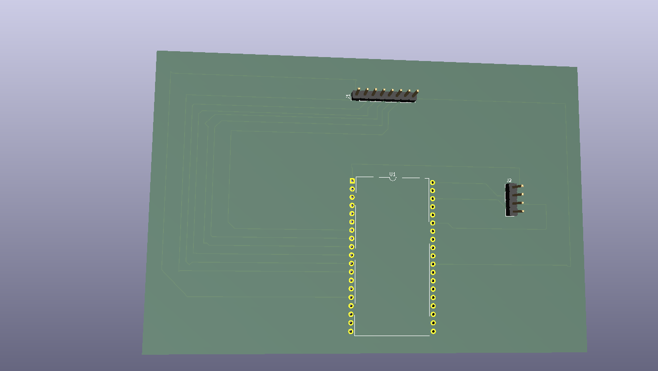
Tic is an open-source printed circuit board by Freshovsky23, from the Freshovsky23/Tic-Tac-Toe repository on GitHub. It is a 2-layer board of 135.5 × 91.5 mm with 3 parts on 38 nets, routed with 75 tracks and 0 vias.
Its parts include 2 connectors and 1 IC. It belongs with the lEDs and displays boards and the ESP8266 boards of this library.
An interactive Tic-Tac-Toe game implemented on the ESP32 microcontroller, utilizing a 4x4 Matrix Keypad for player input and a 20x4 LCD Display (I2C) for the visual board representation.
See the project in action on YouTube: 👉 Watch the Video Demonstration
| Keypad Pin | ESP32 GPIO |
|---|---|
| Row 1 | GPIO 13 |
| Row 2 | GPIO 14 |
| Row 3 | GPIO 27 |
| Row 4 | GPIO 26 |
| Column 1 | GPIO 25 |
| Column 2 | GPIO 33 |
| Column 3 | GPIO 32 |
| Column 4 | GPIO 17 |
| LCD I2C Pin | ESP32 GPIO |
|---|---|
| VCC | 3.3V (VIN) |
| GND | GND |
| SDA | GPIO 21 |
| SCL | GPIO 22 |
To eliminate messy breadboard wiring and create a durable, standalone gaming device, a dedicated dual-layer custom PCB baseboard was designed using KiCad.
1x08 and 1x04 pin headers are placed near the edges for straightforward ribbon cable routing from the keypad and LCD.The complete KiCad design files can be found in the hardware/ directory.
1 | 2 | 3
---------
4 | 5 | 6
---------
7 | 8 | 9| Qty | Value | Footprint | References |
|---|---|---|---|
| 1 | AI-Thinker Nodemcu-32S | ESP32:ai-thinker nodemcu-32s | U1 |
| 1 | Conn_01x04_Pin | Connector_PinHeader_2.54mm:PinHeader_1x04_P2.54mm_Vertical | J2 |
| 1 | Conn_01x08_Pin | Connector_PinHeader_2.54mm:PinHeader_1x08_P2.54mm_Vertical | J1 |
It measures 135.5 × 91.5 mm and has 2 copper layers, 1.6 mm thick.
3 parts. The full list of its parts is on this page, with links to each part's symbol and footprint where PCBKit's library has them.
From the Freshovsky23/Tic-Tac-Toe repository on GitHub, at the commit this page was made from: the board is hardware/tic.kicad_pcb and its schematic hardware/tic.kicad_sch. PCBKit opens the board in the browser, with nothing to install.
Its repository states no licence, so its author keeps all rights: ask Freshovsky23 before reusing the design.

hzeller/rpi-rgb-led-matrix
Controlling up to three chains of 64x64, 32x32, 16x32 or similar RGB LED displays using Raspberry Pi GPIO


atopile/atopile
Design circuit boards with code! ✨ Get software-like design reuse 🚀, validation, version control and collaboration in hardware; starting with electronics ⚡️


hackclub/sprig
🍃 Learn to code by making games in a JavaScript web-based game editor.