4 layers31.4 × 70 mm
UPLC Panel
fredriknk/uPLC-Stack
Quick note, this is then panelization repo, head for the individual repos to get design files.
226 parts9

 fredriknk/esprelay
ESP8266 small signal relay module utilizing an ESP-12-F wifi module for communication and MCU, and has two 2.5-25V inputs, and a single 25v, 100ma high speed open drain output through a TBD062003 DMOS transistor array…
Esprelay is an open-source printed circuit board by fredriknk, from the fredriknk/esprelay repository on GitHub, published under the MIT licence. It is a 2-layer board of 52.3 × 20 mm with 42 parts on 39 nets, routed with 342 tracks and 107 vias.
It is built around the ESP-12F, DS8242-33S5 and DS8242-50S3, with the TBD62003AFWG, 1N4148WS and G6K-2P-Y-DC5 among its other parts. Its parts include 10 resistors, 9 capacitors, 4 ICs, 2 diodes and 2 connectors. It belongs with the ESP8266 boards of this library.


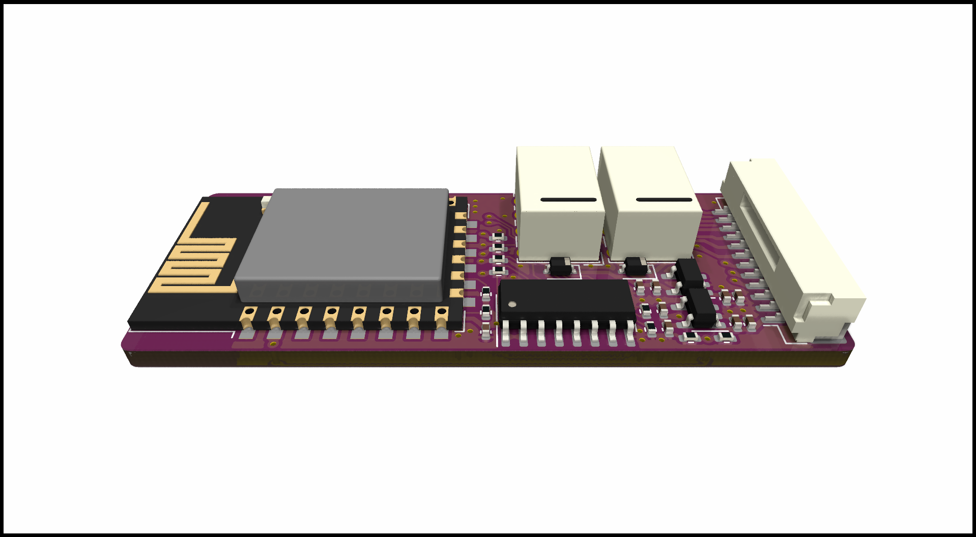
ESP8266 small signal relay module utilizing an ESP-12-F wifi module for communication and MCU, and has two 2.5-25V inputs, and a single 25v, 100ma high speed open drain output through a TBD062003 DMOS transistor array ic. The three relay outputs are capable of driving around 25V 500ma.
Thanks to u/PricelessToolkit/ESPClicker for inspiration. If you need a ready to use product you should so head over to his store and buy his version.
| Parameter | Description |
|---|---|
| Input voltage | 5-15v |
| Current | TBD Wifi: ##mA, Radio Off: ##mA, Deep sleep ##uA |
| Communication | 2.4ghz WIFI, Uart TTL |
| Baudrate | 115200 |
| PCB size | 20x65mm |
| PCB info | 1.6mm FR4, HASL lead free, 4 layer (But works with 2) |
| Case size | XxXxXmm TBD |
| Pin | GPIO | Description |
|---|---|---|
| vcc | - | 5-15v |
| GND | - | Ground |
| HI1 | GPIO4 | 2.5-25v input |
| HI1 | GPIO5 | 2.5-25v input |
| HO1 | GPIO13 | 25v 100ma open drain output |
| R1A | GPIO12 | Relay 1 COM |
| R1NC | GPIO12 | Relay 1 Normally Closed |
| R1NO | GPIO12 | Relay 1 Normally Open |
| R2A | GPIO12 | Relay 1 COM |
| R2NO | GPIO12 | Relay 1 Normally Open |
| R3A | GPIO12 | Relay 1 COM |
| R3NO | GPIO12 | Relay 1 Normally Open |
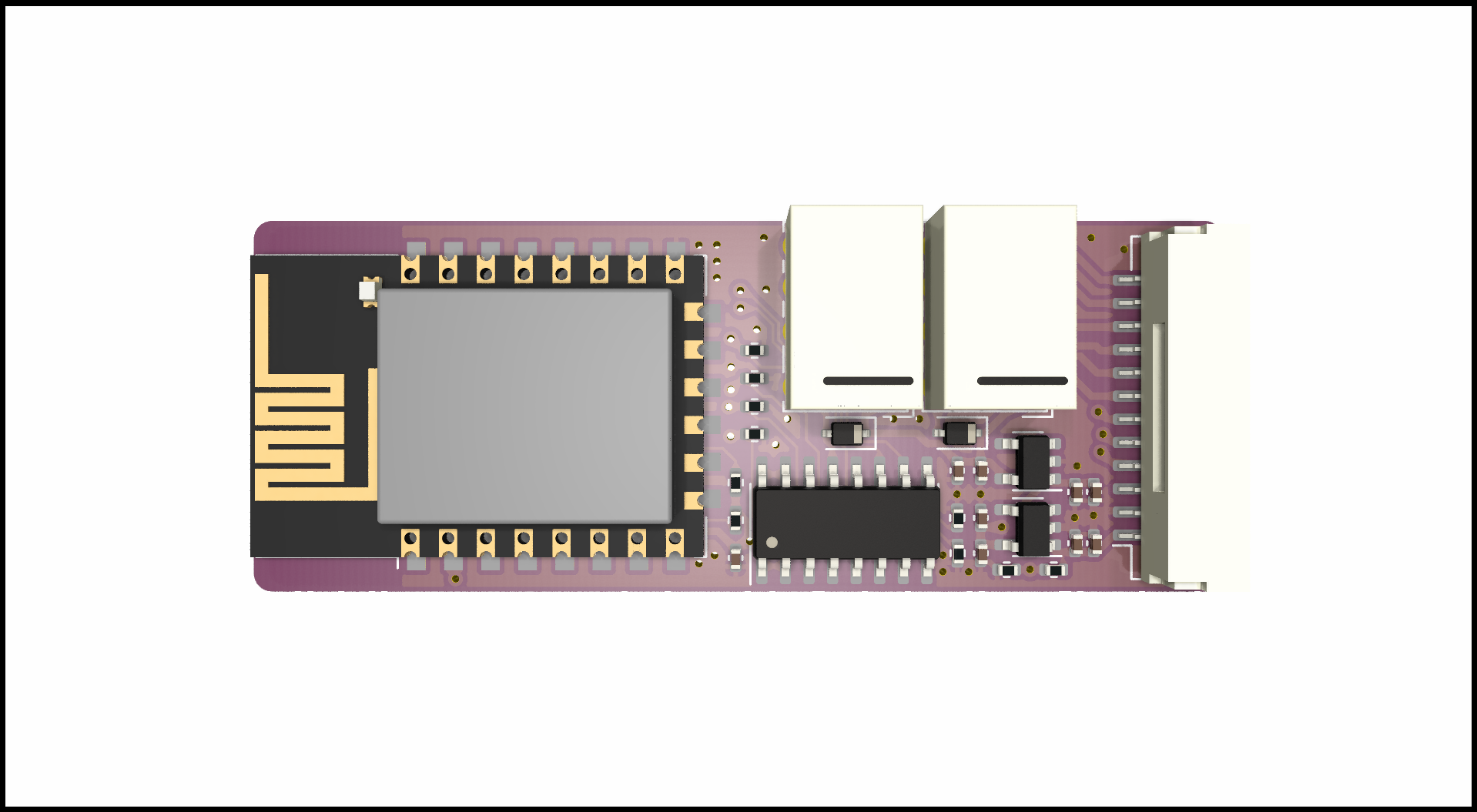
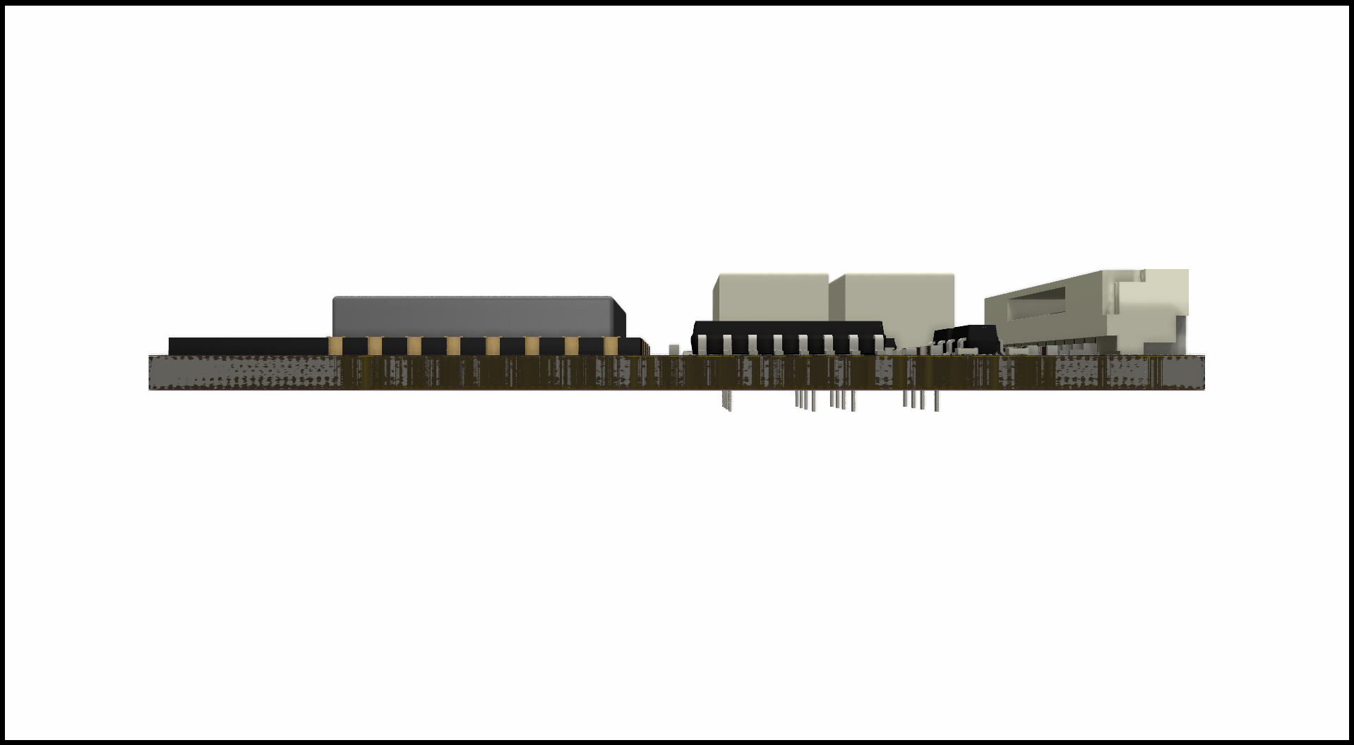
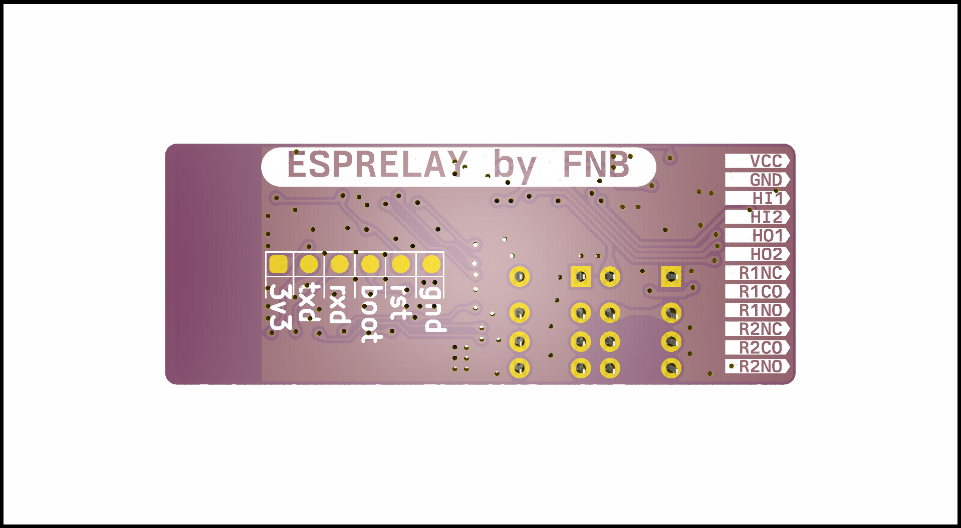
TODO
TODO
| Qty | Value | Footprint | References |
|---|---|---|---|
| 8 | 10K | Resistor_SMD:R_0402_1005Metric | R1, R2, R7, R8, R9, R10, R11, R12 |
| 5 | 0.1uF | Capacitor_SMD:C_0402_1005Metric | C3, C4, C5, C8, C9 |
| 4 | 2.2uF | Capacitor_SMD:C_0402_1005Metric | C1, C2, C6, C7 |
| 2 | 1N4148WS | Diode_SMD:D_SOD-323 | D1, D2 |
| 2 | G6K-2P-Y | Relay_THT:Relay_DPDT_Omron_G6K-2P-Y | K1, K2 |
| 1 | 137k | Resistor_SMD:R_0402_1005Metric | R3 |
| 1 | 316k | Resistor_SMD:R_0402_1005Metric | R6 |
| 1 | Conn_01x06_Pin | TestPoint:TestPoint_Pad_1.0x1.0mm_6pad | J1 |
| 1 | DS8242-33S5 | Package_TO_SOT_SMD:SOT-23-5 | U1 |
| 1 | DS8242-50S3 | Package_TO_SOT_SMD:SOT-23-5 | U2 |
| 1 | ESP-12F | RF_Module:ESP-12E | U3 |
| 1 | G*** | kibuzzard-65666C71 | kibuzzard-65666C71 |
| 1 | G*** | kibuzzard-65CFDABC | kibuzzard-65CFDABC |
| 1 | G*** | kibuzzard-65CFDAA7 | kibuzzard-65CFDAA7 |
| 1 | G*** | kibuzzard-65666C76 | kibuzzard-65666C76 |
| 1 | G*** | kibuzzard-65CFDA91 | kibuzzard-65CFDA91 |
| 1 | G*** | kibuzzard-65666C87 | kibuzzard-65666C87 |
| 1 | G*** | kibuzzard-65666C6B | kibuzzard-65666C6B |
| 1 | G*** | kibuzzard-65CFDAAD | kibuzzard-65CFDAAD |
| 1 | G*** | kibuzzard-65666CB7 | kibuzzard-65666CB7 |
| 1 | G*** | kibuzzard-6566713E | kibuzzard-6566713E |
| 1 | G*** | kibuzzard-65CFDAB5 | kibuzzard-65CFDAB5 |
| 1 | G*** | kibuzzard-65666C7B | kibuzzard-65666C7B |
| 1 | G*** | kibuzzard-65CFDAA0 | kibuzzard-65CFDAA0 |
| 1 | SM12B-GHS-TB(LF)(SN) | Connector_JST:JST_GH_SM12B-GHS-TB_1x12-1MP_P1.25mm_Horizontal | J2 |
| 1 | TBD62003AFWG | Package_SO:SOIC-16_3.9x9.9mm_P1.27mm | U5 |
It measures 52.3 × 20 mm and has 2 copper layers, 1.6 mm thick.
42 parts, built around the ESP-12F, DS8242-33S5, DS8242-50S3 and TBD62003AFWG. The full list of its parts is on this page, with links to each part's symbol and footprint where PCBKit's library has them.
From the fredriknk/esprelay repository on GitHub, at the commit this page was made from: the board is CAD/esprelay/esprelay.kicad_pcb and its schematic CAD/esprelay/esprelay.kicad_sch. PCBKit opens the board in the browser, with nothing to install.
Its repository publishes it under the MIT licence: you may reuse it on that licence's terms (keep the author's notice, and for a copyleft licence share your changes alike).
fredriknk/uPLC-Stack
Quick note, this is then panelization repo, head for the individual repos to get design files.

fredriknk/uPLC-Digital
I now have two prototypes of the uPLC-Digital so ESP-Home integrations will come soon.

fredriknk/uPLC-Relay
I now have two prototypes of the uPLC-Relay so ESP-Home integrations will come soon.

ties1887/Mesh-radio-Halow-LoRa
Modular mesh radio system using Raspberry Pi + HaLow (802.11ah) + LoRa.

fredriknk/uPLC-Analog
I now have two prototypes of the uPLC-Analog so ESP-Home integrations will come soon.

Phunkafizer/RFM-gateway
Hard- and software for the RFM-gateway, a universal platform for integrating sub-GHz radio into your WiFi network

