Skip to the content
PCBKitNew board
2 layers82.4 × 74.6 mmExt, the printed circuit board in 3D

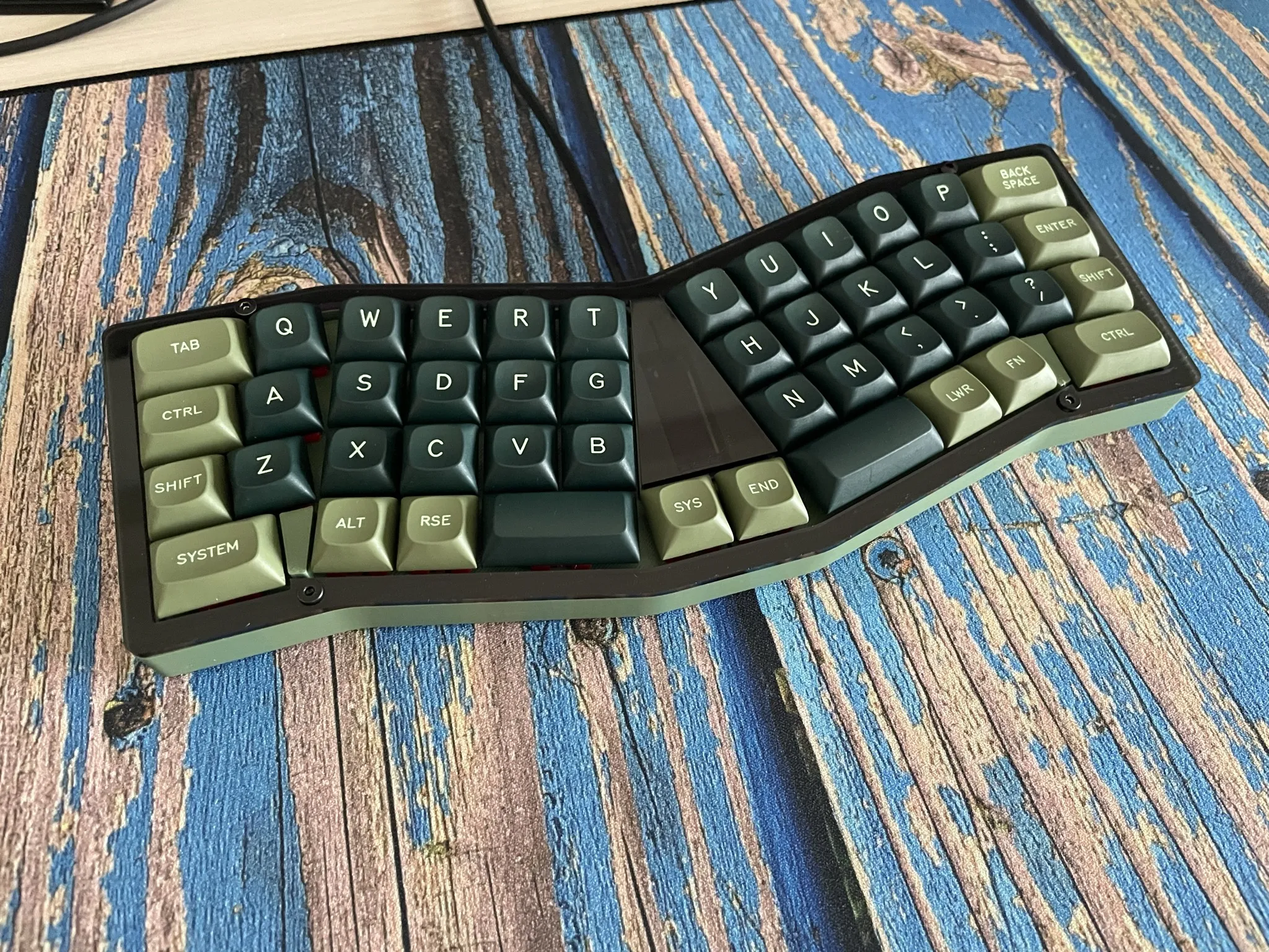
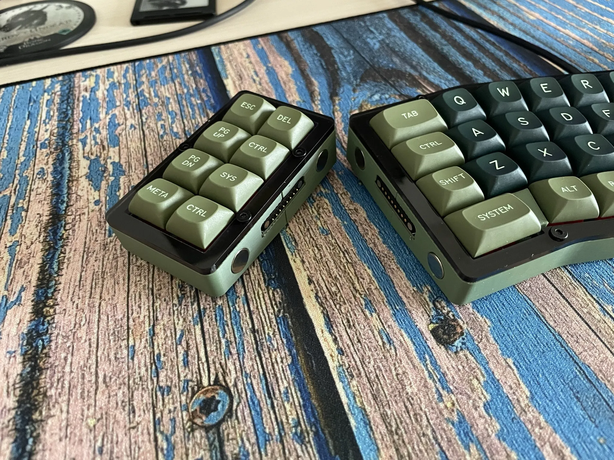
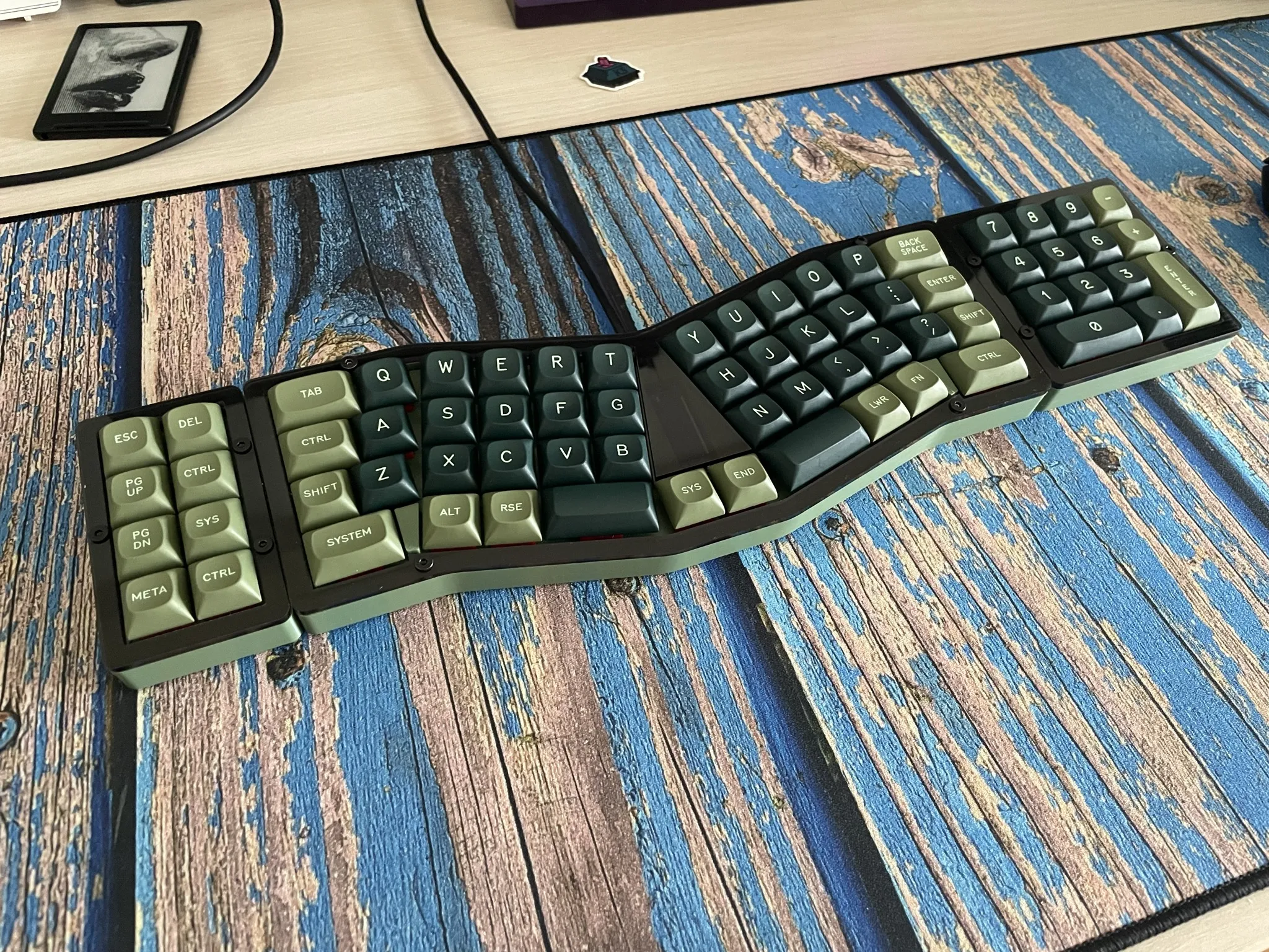
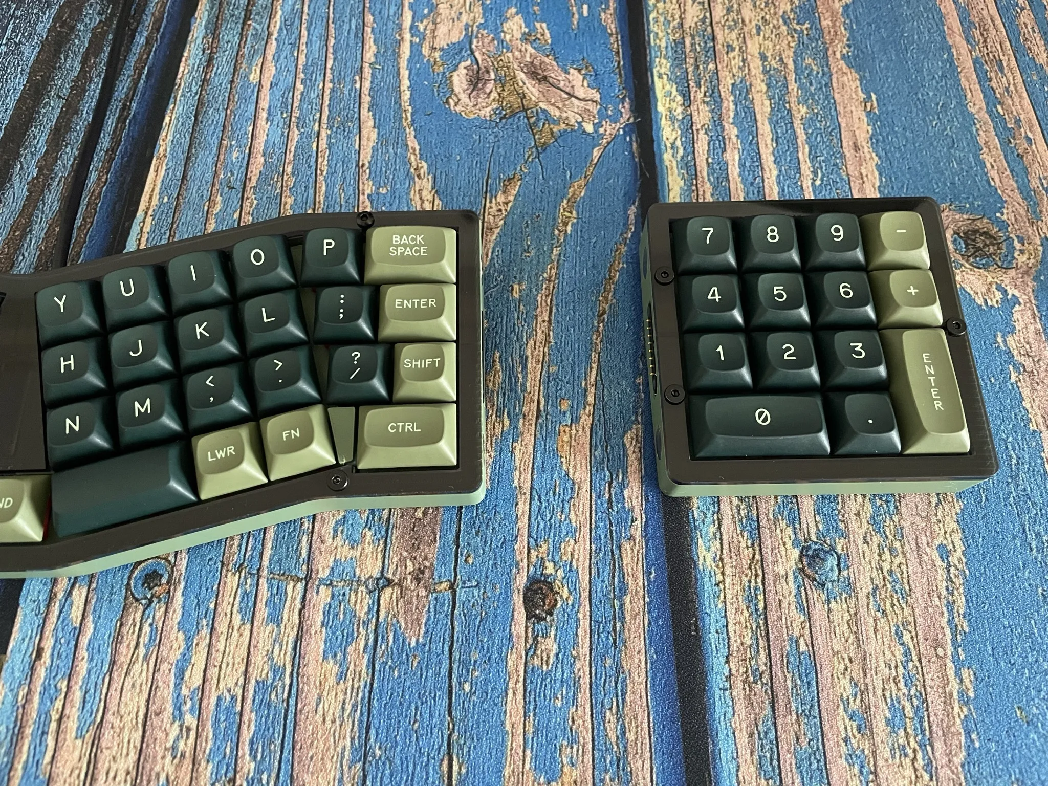
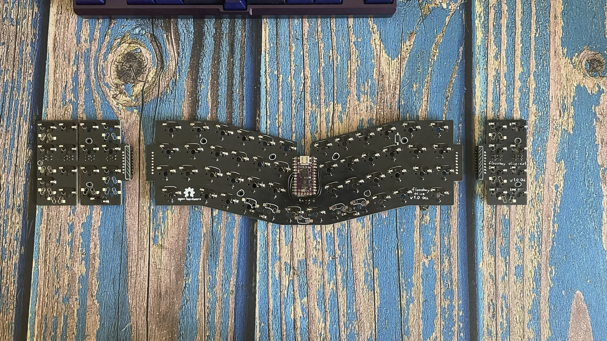
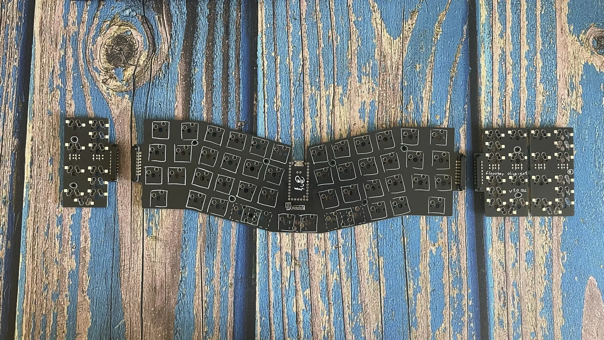
The olice is 40% alice-like ortho keyboard. It features two board extension modules that can be magnetically attached on the sides.

Size
82.4 × 74.6 mm
Copper layers
2
Thickness
1.6 mm
Parts
44
Nets
24
Pads
437
Tracks, vias
247, 20
Routed
Yes
KiCad
KiCad 10.0 (file 20260206)
Created
6 Dec 2025
Updated
4 Jul 2026

Overview

Ext is an open-source printed circuit board by floookay, from the floookay/olice repository on GitHub. It is a 2-layer board of 82.4 × 74.6 mm with 44 parts on 24 nets, routed with 247 tracks and 20 vias.

It is built around the 1N4148WT. Its parts include 16 diodes and 1 connector. It belongs with the keyboards and input boards of this library.

Main components

1

README

README.md

olice

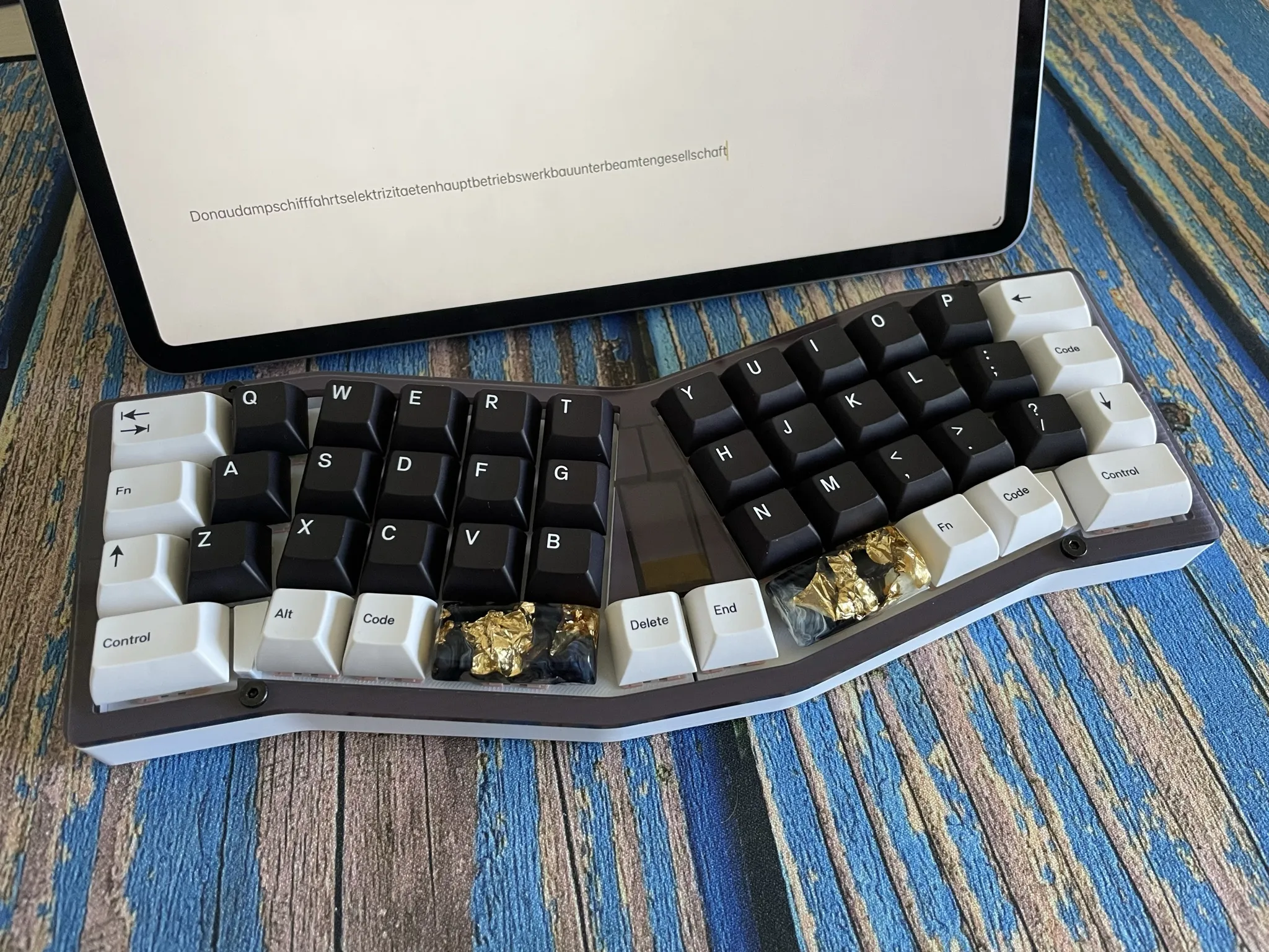
The olice is 40% alice-like ortho keyboard. It features two board extension modules that can be magnetically attached on the sides.

basic pogo extended

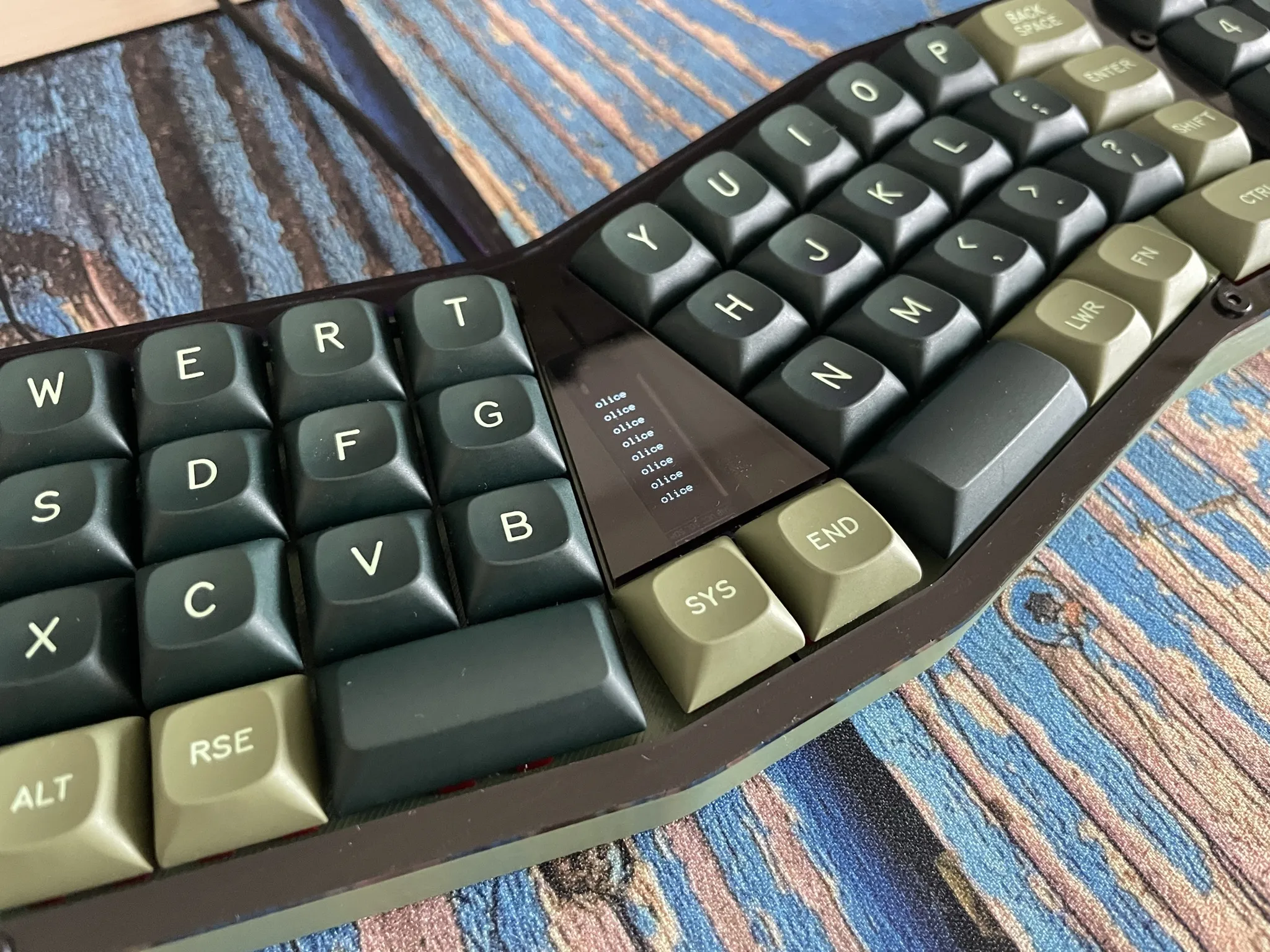
additional pictures

oled numpad bottom ble

layout

https://www.keyboard-layout-editor.com/#/gists/c1cd375404f84e521f4a214a25ba4b32

Keycap compatibility is best with uniform profiles or keycaps that use the same profile on the home row as on the bottom row. R2 1.25u keycaps are otherwise rather unusual.

pcb

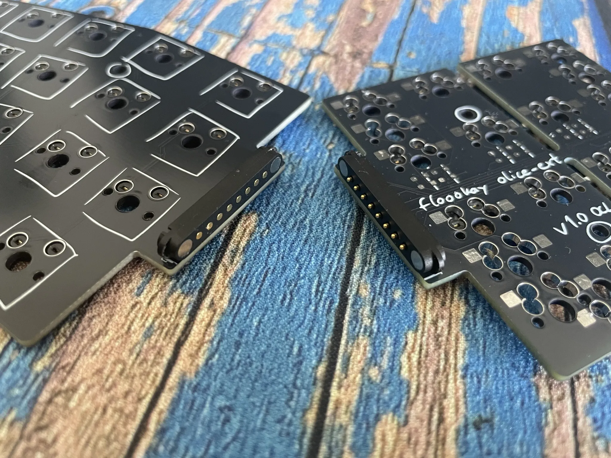
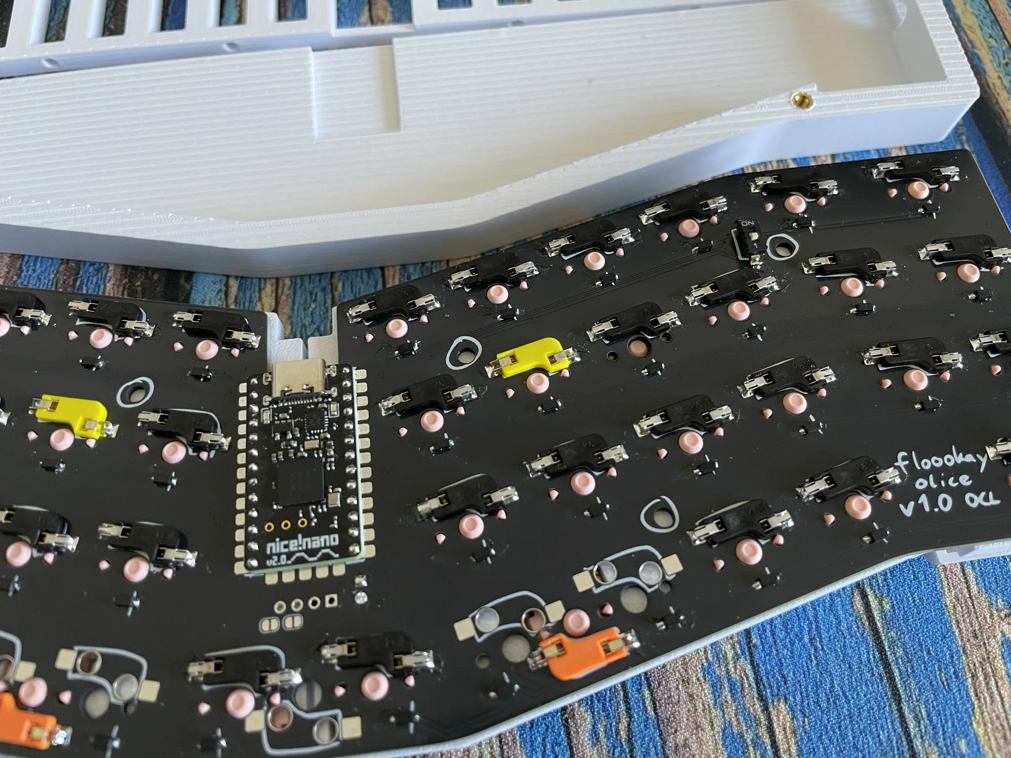
The keyboard is powered by a 0xCB Helios and the pogo pin connectors extend the matrix to the extension modules.

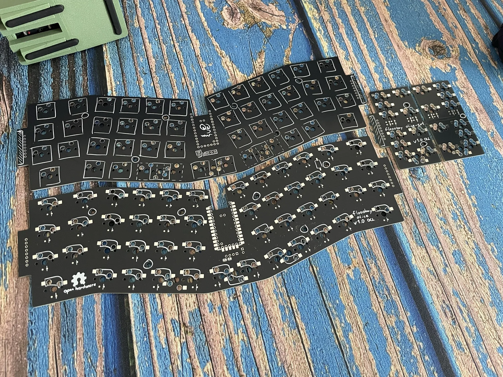
naked pcb

additional pictures

bottom top pogo oled

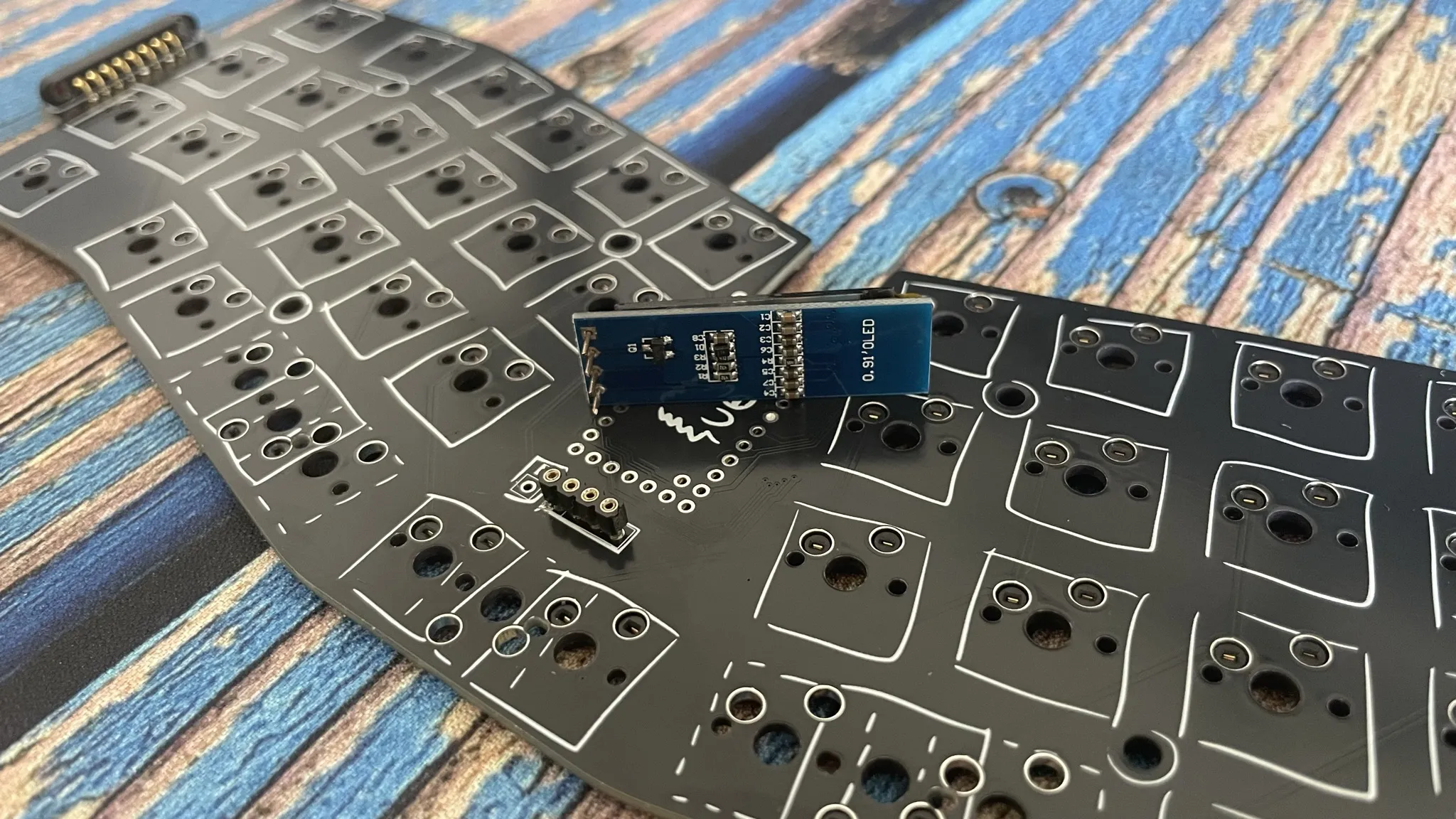
(don't mind the bodge wires on the oled header, I had the footprint flipped on v1.0, it's fixed now)

case

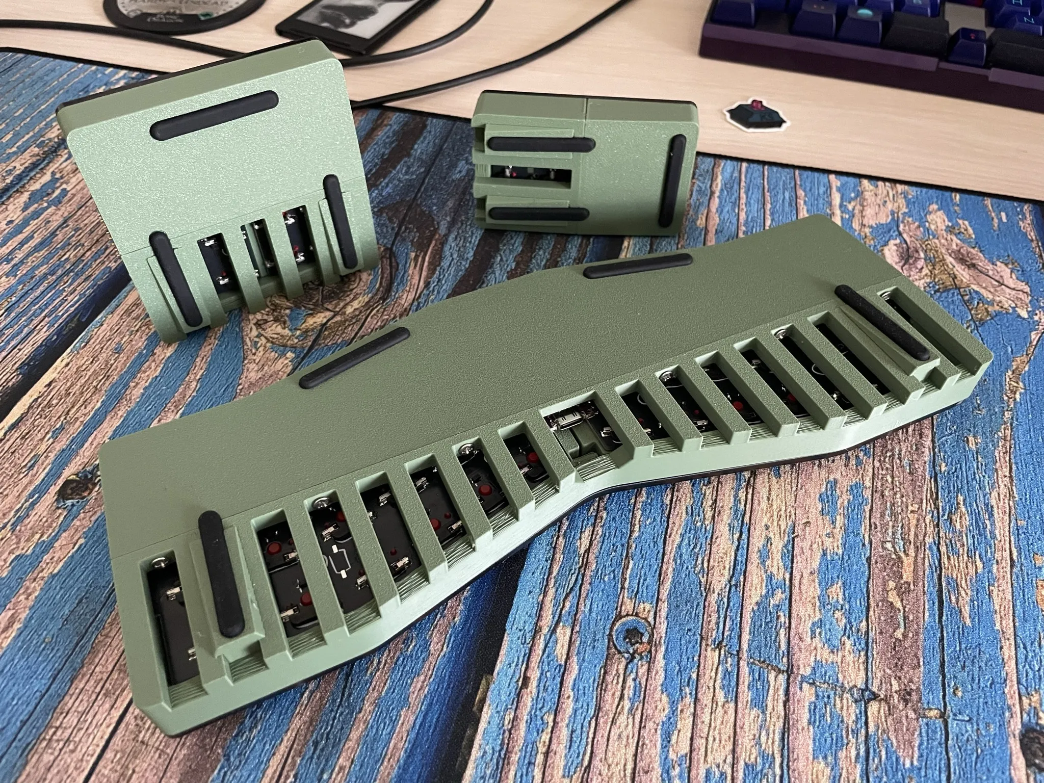
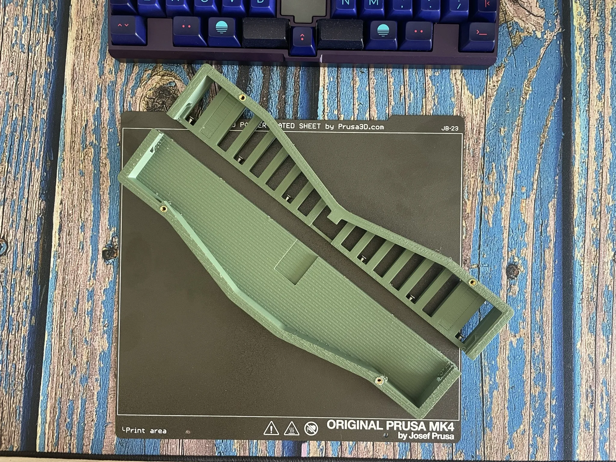
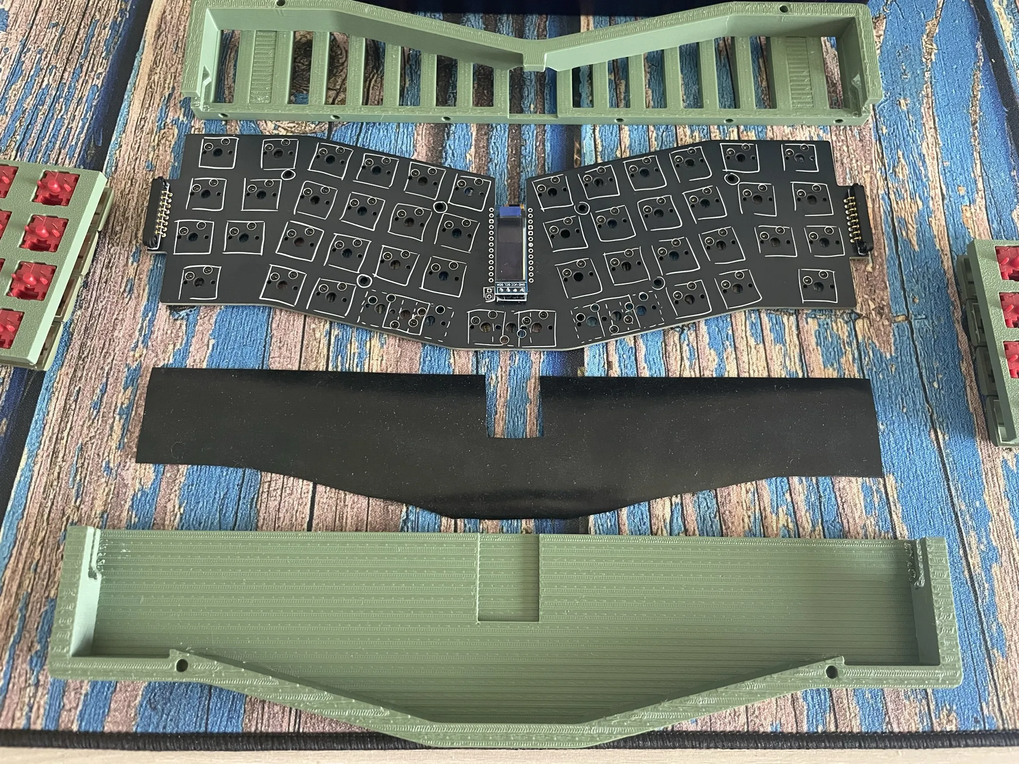
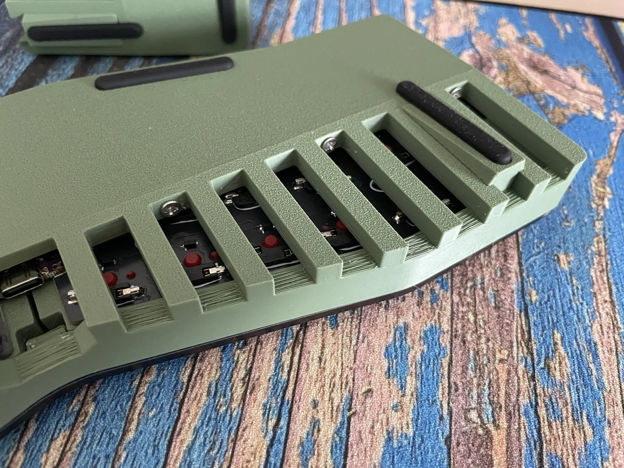
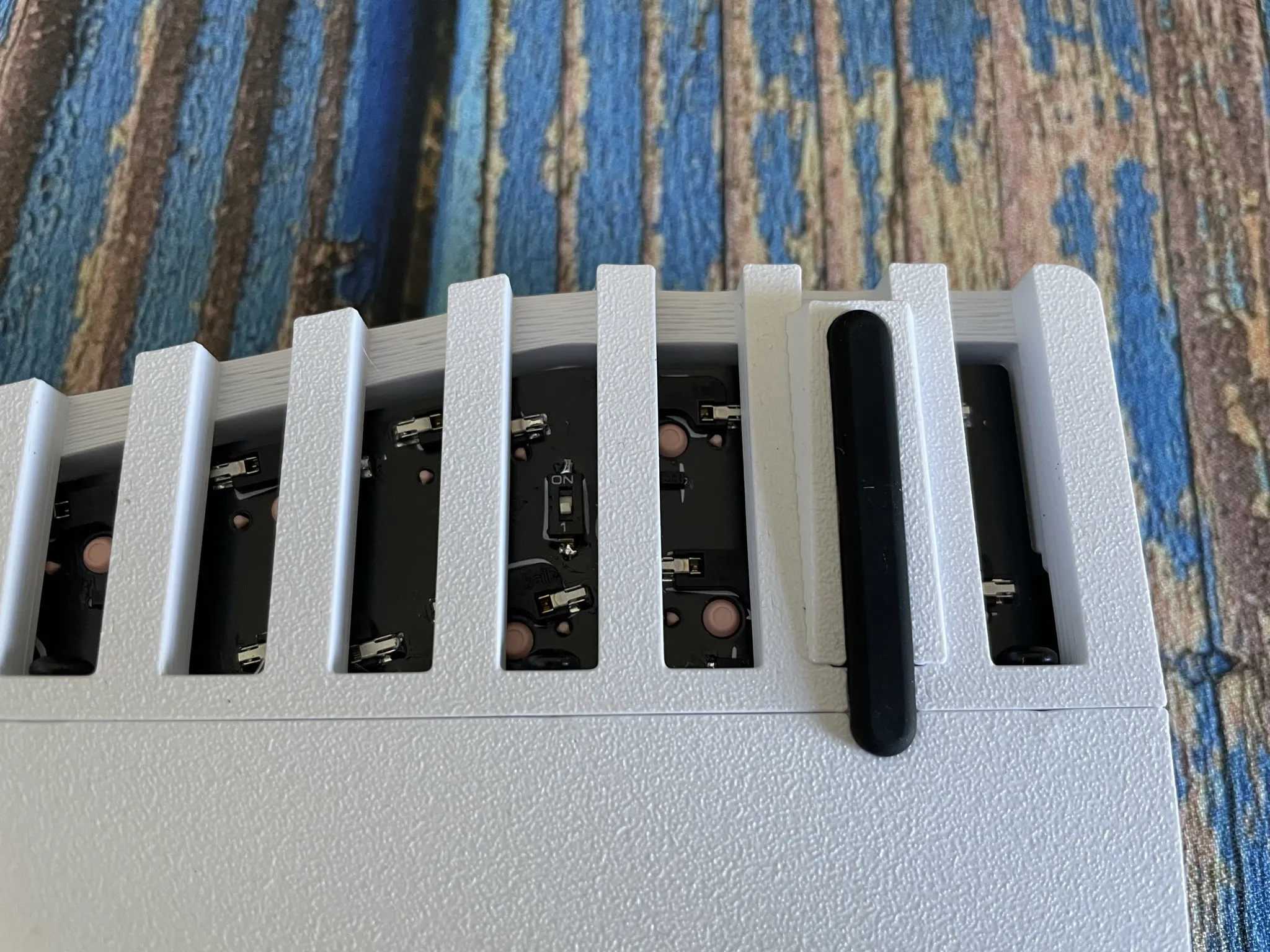
The case is 3d printed with an acrylic top layer. The board is kinda sandwich mounted via the extension connection holes on each side and has no other mounting points. I used a sheet of rubber to minimize flex. The extensions have additional mounting posts so the board doesn't fall out.

Your 3d printer needs at least a bed size of 250x210 and I printed mine with 100% infill and 0.2mm layer height.

firmware

The keyboard can be powered by QMK or ZMK:

assembly

additional pictures

printing case feet bottom

also see additional pcb pictures

main

  1. Start with flashing the firmware to the Helios.
  2. Then solder the main board, I'd start with soldering the diodes and hot swap sockets, then continue with soldering the controller (don't use a header, solder it directly to the pcb).
  3. Then put the pogo pin connectors into the top side and solder them from the bottom (like the sockets and diodes), make sure they are flush with the border of the pcb.
  4. Solder the OLED header on the same side. I recommend the hot swap header so you can easily remove the plate without having to remove all switches first.
  5. Insert some leftover wire into the oled pin header socket and solder them to the oled display. Make sure that you're not soldering it to the hot swap header, don't apply too much solder.
  6. Click the switches into the plate and install them onto the pcb. Plug the pcb into your PC and test every key
  7. Melt the 10 heat set inserts into the case
  8. Cut the thin sheet of rubber to the correct size of the front case piece and put it there
  9. Slide the pcb into both case pieces and secure it via the 6 screws on the back
  10. Put the acrylic cover on and screw it in
  11. Put some glue in the magnet pockets and secure the disc magnets

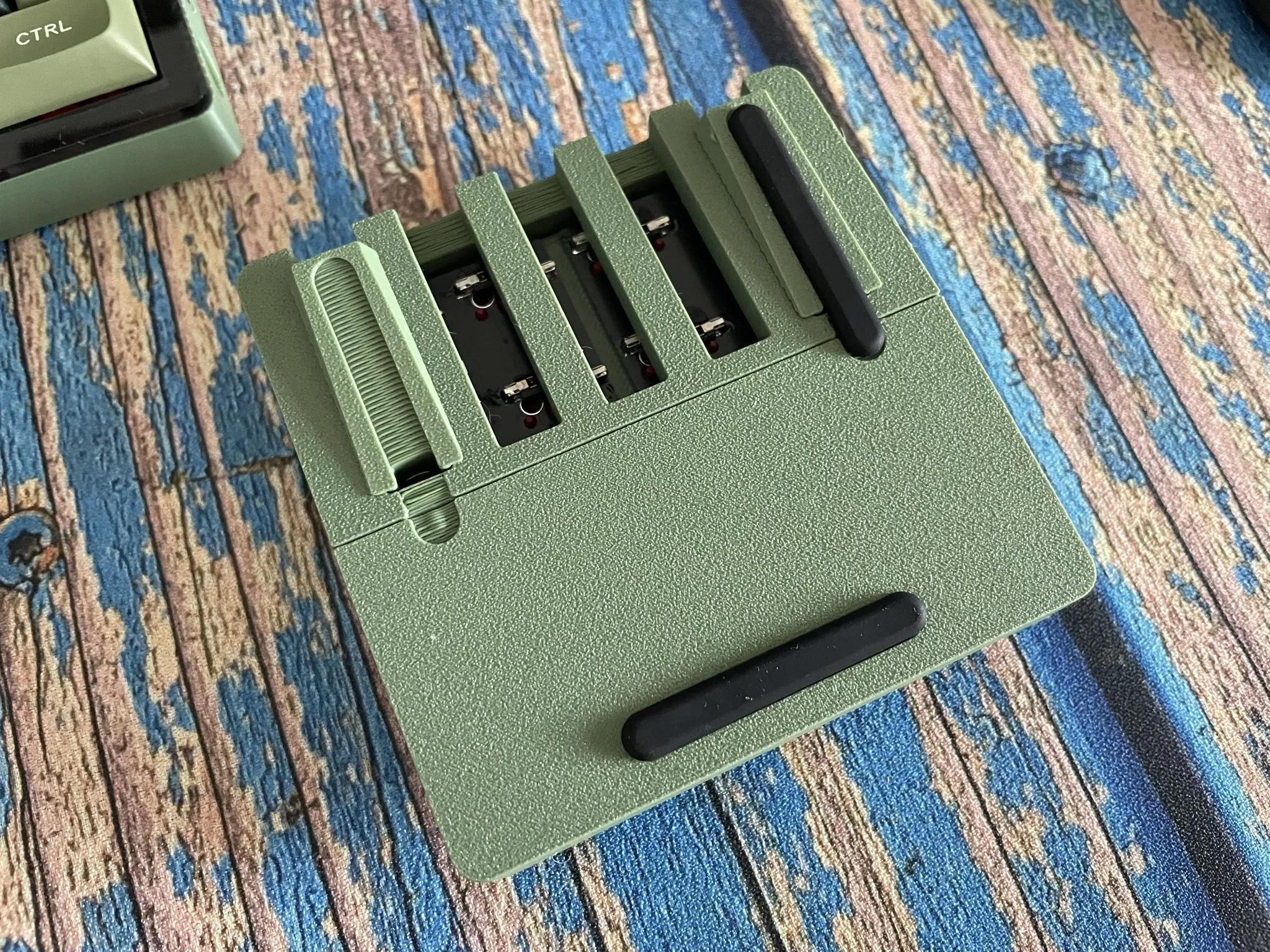
extension 4u

  1. Select on which side you want to use the extension and mark it. This is the top side, the only thing that is later going onto this side is the pogo pin connector.
  2. Flip the pcb and solder the hot swap sockets and diodes. The diode placement is a bit tricky, I'd start with soldering the inner pads, then securing the diode, then moving to the next diode.
  3. Then put the pogo connector into the top side and solder it from the bottom side (like the sockets and diodes), make sure they are flush with the border of the pcb.
  4. Install all but one heat set inserts into the two case pieces. The split-in-half heat set insert hole is going in later
  5. Click the switches into the plate and install them onto the pcb
  6. Slide and wiggle the pcb into both case pieces with the pcb posts and and secure it via the screws on the back
  7. Install the split-in-half heat set insert in the now closed hole
  8. Put the acrylic cover on and screw it in
  9. Put some glue in the magnet pockets and secure the disc magnets. Make sure that the orientation of the disc magnets matches the orientation of the disc magnets on the main case.

extension 2u

  1. Select on which side you want to use the extension and mark it. This is the top side, the only thing that is later going onto this side is the pogo pin connector.
  2. Break off the additional columns and file the excess pcb flat if neccessary.
  3. Continue with step 2. from extension 4u

BLE version

bom (additional)

The oled module is not supported and because of the limited pins on the controller only 2u extensions are supported. Please note the following differences during assembly:

  1. Close both jumper pads if you want to use a 2u extension. This makes the pins that were previously used by the oled display usable as matrix rows.
  2. The nice!nano doesn't have castellated holes so I'd recommend using some leftover wire pieces and soldering it from both sides shortly to ensure a good connection.
  3. Solder the on/off switch and turn it off
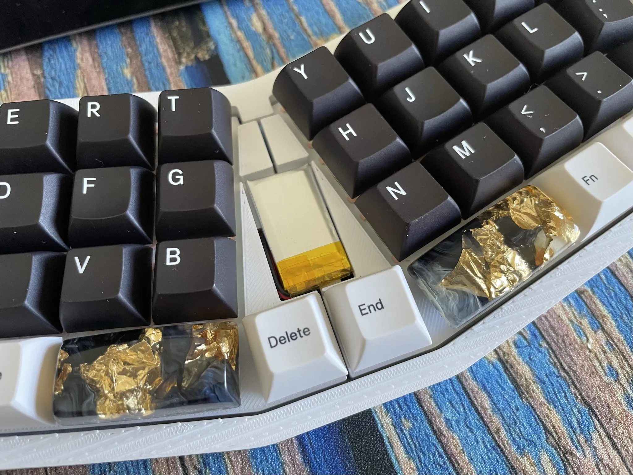
  4. Solder the battery to the 2-pin header area, the square hole is b-
additional pictures

testing pcb switch battery

Parts

44
QtyValueFootprintReferences
22MX_SW_HSolice:SW_MX_HS_S_CPG151101S11_1u_reversibleMX1, MX2, MX3, MX10, MX11, MX12, MX13, MX14, MX15, MX16, MX17, MX18, MX19, MX20, MX21, MX22 +6
161N4148WTolice:D_SOD-123FVD1, D2, D3, D4, D7, D8, D9, D10, D13, D14, D15, D16, D19, D20, D21, D22
2LOGOLOGOG***, G***
1
1Conn_01x08olice:pogo_header_1x08_P2.54mm_HorizontalJ2

The 42 most common of 44 parts.

Questions

How big is the Ext PCB?

It measures 82.4 × 74.6 mm and has 2 copper layers, 1.6 mm thick.

What parts does the Ext use?

44 parts, built around the 1N4148WT. The full list of its parts is on this page, with links to each part's symbol and footprint where PCBKit's library has them.

Where can I download the Ext KiCad files?

From the floookay/olice repository on GitHub, at the commit this page was made from: the board is pcb/ext/ext.kicad_pcb and its schematic pcb/ext/ext.kicad_sch. PCBKit opens the board in the browser, with nothing to install.

Can I use the Ext design in my own project?

Its repository states no licence, so its author keeps all rights: ask floookay before reusing the design.

More from floookay/olice

1
  • 2 layers275.5 × 92 mmOlice, the printed circuit board in 3D

    Olice

    floookay/olice

    The olice is 40% alice-like ortho keyboard. It features two board extension modules that can be magnetically attached on the sides.

    115 parts33

Similar boards

  • 2 layers181 × 97 mmOpenDeck r3.1.2, the printed circuit board in 3D

    OpenDeck r3.1.2

    shanteacontrols/OpenDeck

    A platform for building interactive control and sensing devices using MIDI and OSC built with Zephyr RTOS.

    262 parts960Apache-2.0
  • 2 layers255.9 × 99.3 mmZerosprey42, the printed circuit board in 3D

    Zerosprey42

    beekeeb/zerosprey42

    Zerosprey42 Keyboard is a wired, beginner friendly, choc hotswap, MonoBlockSplit (Unibody), column-staggered, DIY mechanical keyboard.

    96 parts140
  • 4 layers65 × 56.5 mmSH RPi, the printed circuit board in 3D

    SH RPi

    hatlabs/SH-RPi-hardware

    Sailor Hat for Raspberry Pi hardware design files

    168 parts56
  • 2 layers59.6 × 42 mmMacropad synthplug mk2, the printed circuit board in 3D

    Macropad synthplug mk2

    todbot/macropadsynthplug

    Turn StemmaQT port by into Audio Out + MIDI In

    43 parts53CC0-1.0
  • 4 layers47 × 39.5 mmStealthburner Toolhead PCB, the printed circuit board in 3D

    Stealthburner Toolhead PCB

    acha666/RP2040_ToolheadPCB_SB

    A Toolhead PCB for VORON StealthBurner based on RP2040

    145 parts43GPL-3.0
  • 2 layers271.8 × 103.9 mmHotswap ble, the printed circuit board in 3D

    Hotswap ble

    ebastler/cornholius

    ZMK-based replacement PCB for Cornelius keyboard

    146 parts37
  • 4 layers35.5 × 14.5 mmComplete v1.0, the printed circuit board in 3D

    Complete v1.0

    drpykachu/Sonar-Watch

    A self-designed, home-made watch intended to tell time in a funky and unique way!

    225 parts23
  • 4 layers94.3 × 52.8 mmJetbot mini, the printed circuit board in 3D

    Jetbot mini

    NVIDIA-AI-IOT/jetbot_mini

    While developing the schematic and layout designs, I used some footprints from SnapEDA; in order to avoid dealing with licensing issues, I will not redistribute those files on this Github and instead link to where you…

    188 parts23