2 layers216.9 × 86.8 mm
Sweepv2
davidphilipbarr/Sweep
Sweep - a small promicro based keyboard inspired by the Ferris.
51 parts2.1k
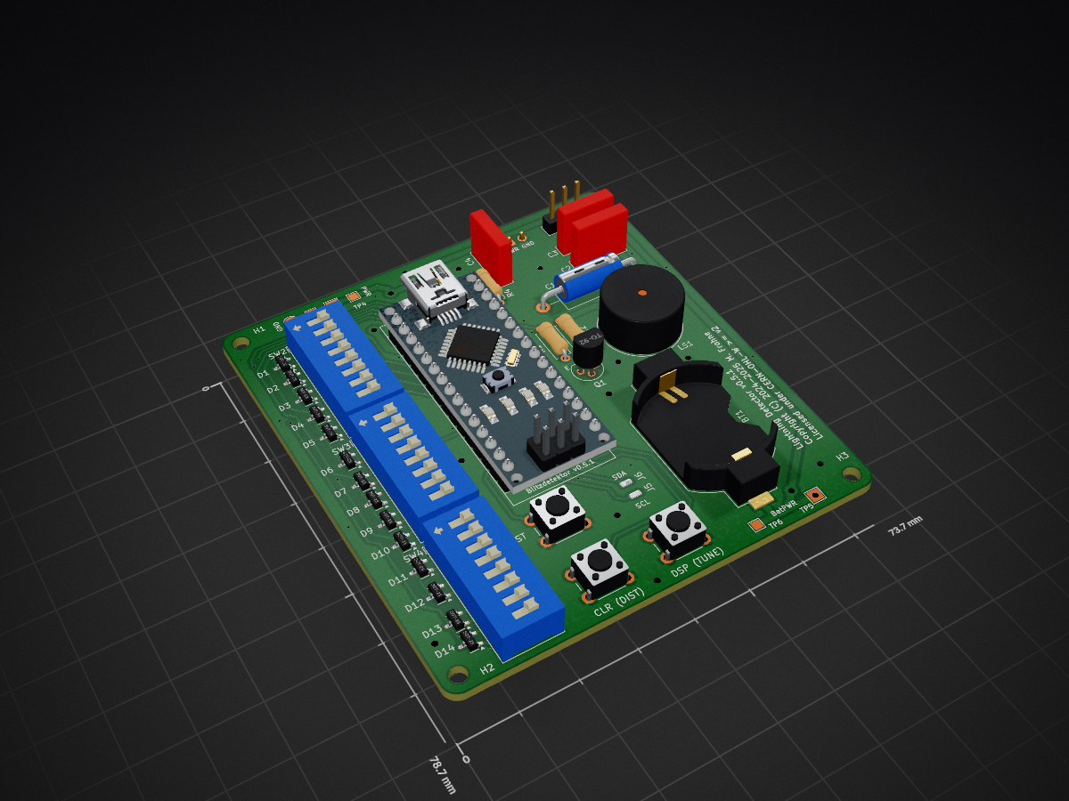
 flooklab/Lightning_Detector1
An experimental open hardware project for early notification about approaching thunderstorm activity
Lightning Detector is an open-source printed circuit board by flooklab, from the flooklab/Lightning_Detector repository on GitHub. It is a 2-layer board of 73.7 × 78.7 mm with 51 parts on 50 nets, routed with 320 tracks and 99 vias.
Its parts include 14 diodes, 7 connectors, 7 switches, 4 capacitors and 4 resistors. It belongs with the radio and wireless and sensors and measurement boards and the AVR (ATmega, ATtiny) boards of this library.
Lightning Detector is an experimental open hardware project for early notification about approaching thunderstorm activity.
It is a battery-powered (1x or 2x CR2032) device with low power consumption in mind and is based on an Arduino Nano 33 BLE
as microcontroller unit (MCU) and the AS3935 "Franklin Lightning Sensor" chip by AMS/ScioSense as main detector element.
For license information please see the License Information section at the bottom.
! ! ! ! ! WARNING ! ! ! ! !
Do NOT actually use Lightning Detector as a serious device to warn you about lightnings or thunderstorms!
It might be that lightnings will NOT be detected and that you will NOT be notified about present or
approaching thunderstorms. You have to assume that the device is inherently UNSAFE and does NOT
work properly. There is NO guarantee for the fitness for any particular purpose whatsoever.
UNDER NO CIRCUMSTANCES should you trust the information provided (or not provided) by the device.
Lightning Detector might NOT be tested thoroughly enough and is NOT even intended to be a reliable detector device.
Note that being in a thunderstorm (especially without sufficient protection around you (such as a building))
is a very dangerous situation as you might suddenly be struck by lightning, which is potentially LIFE-THREATENING.
Generally, you should always try to combine multiple sources of information to assess the current risk of thunderstorms
and lightning strikes. Check the weather forecast and watch the sky. Dark clouds can be an early indicator.
If in doubt (or when there is/are audible thunder or visible lightnings at the latest), please seek shelter!
! ! ! ! ! WARNING ! ! ! ! !
See also below DISCLAIMER AND LIABILITY - OHL-W and - GPL and - OFL!
The AS3935 detects lightning strikes indirectly by means of their accompanying electromagnetic radiation,
which is claimed to work up to a maximum distance of 40 kilometers according to its datasheet. For every
lightning that is detected by the AS3935 the Lightning Detector is going to generate an acoustic notification
(buzzer beep). Additionally, information such as accumulated lightning count and estimated "thunderstorm distance"
etcetera may be shown on a connected display. You may also establish a serial connection via the Arduino USB
connector to read debug information such as detailed data for every lightning and battery voltage etcetera.
A number of internal settings of the AS3935 can be configured/tweaked via DIP switches in order
to individually optimize detection efficiency and false positive rejection. For a more detailed
overview about the usable features of Lightning Detector please refer to the below sections
Configuration / Modification and Usage.
This project consists of two main components:
To assemble and use the Lightning Detector the following additional active components are required:
Arduino Nano 33 BLE (Rev1):
See for instance here.
SparkFun Lightning Detector AS3935 (or an equivalent unit containing an AMS/ScioSense AS3935 chip and appropriate antenna):
See for instance here.
Waveshare 1.54inch e-Paper Display [optional, display usage can be configured/disabled, see below]:
See for instance here.
SparkFun 16 I/O Expander Breakout SX1509 (or an equivalent unit containing a Semtech SX1509 chip) [optional, required if the above display is used]:
See for instance here.
You should be able to make or order a Lightning Detector PCB using the contents of the Hardware/ directory.
In particular, there are KiCad and also Gerber files, which should enable you to do this.
To assemble the PCB you should use the parts listed in the bill of materials (BOM) in Hardware/BOM/.
In Hardware/Render_Images/ there are render images that can be used as a reference for assembly.
Notes about direct soldering of the Arduino:
J1, J7 and R3 must be installed before A1 (the Arduino), unless you choose the pin socket variant mentioned above.SJ4 on the Arduino board.
This is, of course, also only possible before installing the Arduino to the Lightning Detector PCB, so keep this in mind!
Again, if you choose the pin socket variant for the Arduino, this can be fixed later. Note that with the cut jumper the
USB connector will not be able to provide power anymore, which is why you will then have to provide power over the
Lightning Detector PCB before being able to program the Arduino or otherwise use the USB serial connection.Further notes:
J1, J2 and J7 must be soldered with a slight angle with respect to the
PCB to leave enough space for jumper cables to be connected without interfering with other components' pins.
It is particularly helpful to limit the length of the Arduino pin ends sticking through to the
bottom side by deliberately soldering the Arduino at an increased distance to the board.J2 and J7 (for I2C) are meant for powering and controlling the display. If you decide to use
Lightning Detector without a display (see Firmware Building below), they can be left out.Connecting the "periphery" modules can be simply done via jumper cables.
The SparkFun AS3935 module must be connected to pin header J1. Its pins map to the module pins as follows:
(PWR -> 3V3), (SCK -> SCK), (GND -> GND), (IRQ -> INT), (MISO -> MISO), (MOSI -> MOSI), (SEL -> CS)
For reasons of power saving you should disable the power LED on the SparkFun AS3935 module by cutting the "LED" jumper JP5 there.
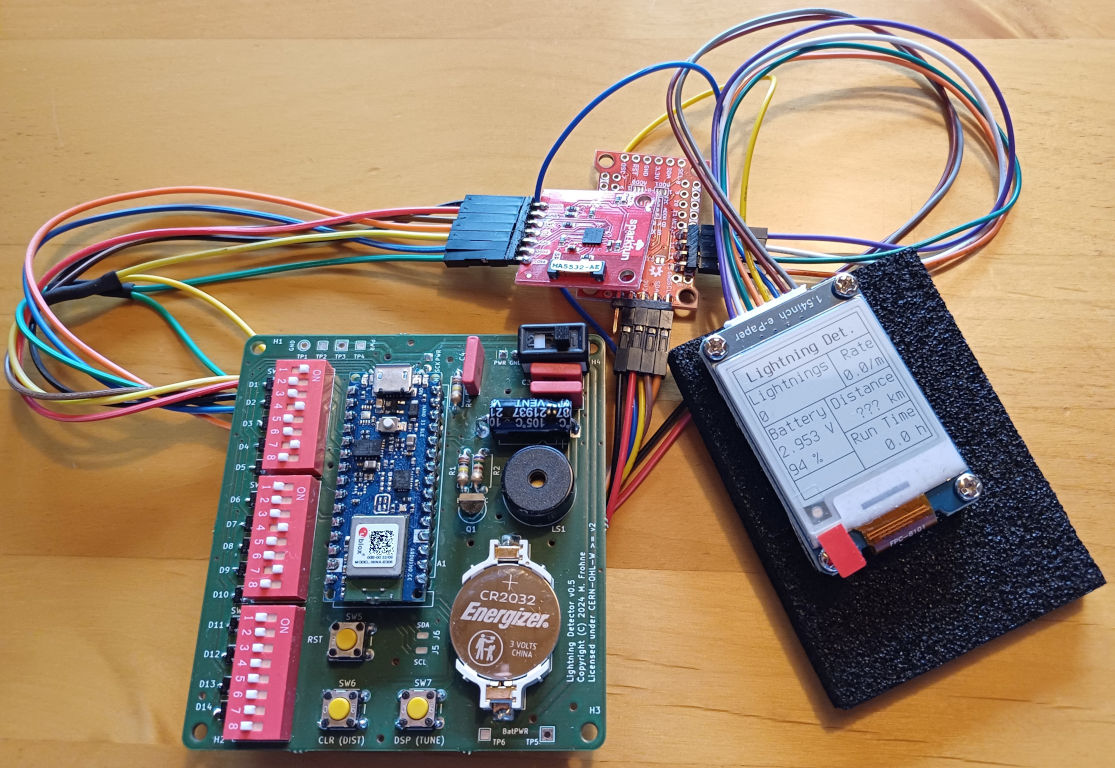
If the pre-defined display configuration (i.e. Waveshare 1.54inch e-Paper Display + SparkFun 16 I/O Expander Breakout SX1509) is going to be used, you can proceed as follows:
J2 and J7 should be connected to the power and I2C pins of the SparkFun SX1509 module, respectively:PWR -> 3V3), (GND -> GND), (SCL -> SCL), (SDA -> SDA)#12 through #15 of the SX1509 module are connected to the e-Paper module like this:#12 -> BUSY), (#13 -> RST), (#14 -> DC), (#15 -> CS)VCC and GND) may either be connected to J2 as well
(using split jumper cables) or simply to the spare 3V3 and GND pins on the SX1509 module.J1
must also be connected to the corresponding e-Paper module pins (using split jumper cables):SCK -> CLK), (MOSI -> DIN)The final assembly may look similar to this:
In Hardware/Case/ there are CAD files for a 3D-printable case that can be
used if all above-mentioned additional periphery modules are attached to the back of the PCB
in a particular layout using the mounting holes and appropriate spacers, as can be seen below:
 |  |  |
Note that in this configuration the AS3935 is very close to the rest of the electronics,
which had caused frequent false positive lightning interrupts in my case. This was successfully
suppressed by inserting a grounded sheet of copper foil between the PCB and the attached periphery.
Building and uploading the firmware can be accomplished with the Arduino IDE (tested with Arduino IDE 1.x, but should also work with Arduino IDE 2.x):
Firmware/lightning_detector/lightning_detector.inoSJ4 was cut (see Hardware Assembly above), power up the Lightning Detector deviceDepending on your operating system, your Arduino IDE version and your preference, you might have to make sure that you additionally have the following software components installed, prior to building the firmware:
mbed MCUs (including the Arduino Core API)arm-none-eabi target platform (including Newlib)Those can be either installed using the Arduino IDE board manager (simply look for "Mbed OS Nano Boards" and/or "Arduino Nano 33 BLE"), or by yourself using existing packages provided by your operating system distribution or directly from the mentioned sources.
Before building the firmware you may want to do some code modifications, the most important/interesting of which are listed in the following:
Use different SX1509 I/O pins:
If desired, the specific I/O pin numbers of the SX1509 that are used for the e-Paper module signals BUSY, RST, DC and CS
may be changed in the file pins.h (within the namespace SX1509Pins).
Disable display usage:
If no display is going to be connected, set the USE_DISPLAY macro in usedisplay.h to USE_DISPLAY_NONE.
Use a different display:
The display part of the firmware is somewhat modular so that it is basically possible to use a completely different display module
by "simply" writing a dedicated driver class implementation for it, which can of course be modified from the existing display driver
(see display_waveshareepaper154bw_sx1509ioexpander.h
and display_waveshareepaper154bw_sx1509ioexpander.cpp).
Furthermore, you will need to make the following changes:
usedisplay.h and assign it to USE_DISPLAY there.display.h using the previously added macro.lightning_detector.ino file (search for USE_DISPLAY).General tweaks:
At the top of lightning_detector.ino, right before the declaration of
the interrupt flags, there are a bunch of constant definitions, which can be adjusted to your liking, such as, for instance:
buzzerFreq: Buzzer beep frequencybuzzerLightBeepSecs: Buzzer beep duration for lightning notificationlightRateAvrgMins: Minimum averaging time to determine current lightning ratesystemMinVoltage: Largest minimum allowed operating voltage for any system componentsystemMaxCurrent: Maximum system current (e.g. during beep or display update)systemBatteryCount: Number of installed coin cellsFirmware code documentation can be generated using Doxygen
(there is a Doxyfile in Documentation/Firmware/).
DIP switch settings:
Make sure to set the DIP switches to the default configuration before use. From left to right (D1 to D14) this is:
Register AFE_GB NF_LEV WDTH SREJ TUN_CAP LCO_FDIV MIN_NUM_LIGH
Value    10010  010    0010 0010 0000    00       00
Note 1: The default amplifier gain setting AFE_GB is recommended for indoor use. For outdoor use they recommend 01110 instead.
Note 2: The optimal "default" TUN_CAP setting is later determined via the antenna tuning procedure (see below).
The above default is just an arbitrary starting point.
The register settings can of course be tweaked as you like. For the meaning/effect of each register please refer to the AS3935 datasheet.
Antenna tuning:
The AS3935 module antenna needs to be tuned to the resonance frequency of 500 kHz +- 17.5 kHz before use.
This can be achieved with the antenna tuning mode (see below).
There are three different "run modes" that can be selected at startup:
The default mode is the Normal mode. Just power up the device to use this mode.
The Normal mode can be overridden at startup by pressing the CLR (DIST) button (UnmaskDisturbers) or the DSP (TUNE) button (TuneAntenna) when/until
the second short buzzer beep is played. There is a first short buzzer beep followed by a 500 ms delay that enables you to press the buttons in time.
Normal:
In the Normal mode the main functionality is the lightning notification. Whenever the AS3935 detects a lightning signal the
Arduino wakes up from sleep mode (which is used most of the time) via interrupt request and then there is going to be a buzzer
beep and a short red blip of the RGB LED on the Arduino board. After that the Arduino goes to sleep mode again to save power.
Other wake-up reasons (i.e. available functionality) are one of the two push buttons (CLR (DIST) or DSP (TUNE)) being pressed,
other AS3935 IRQ events and a recurring timer timeout (see explanations below). All of the AS3935 interrupts produce a
red RGB LED blip, pressed buttons produce a green RGB LED blip and the timer wake-up produces a blue RGB LED blip.
Using the lightning interrupts the total number of lightnings is counted and an average lightning rate is calculated.
Also the estimated storm distance is read for every lightning interrupt and for the dedicated "distance changed" interrupts
(purely age-based statistics evolution). All of this information (and more) can be displayed on the display on request
(see below), including, which was the last AS3935 interrupt. Note, in that regard, that there is also an interrupt
for too much antenna/amplifier noise. This does not have any direct effect other than the LED blips but can thus
of course be checked for on the display. Note that the disturber signal interrupts are disabled in this mode.
The timer wake-up is used (a) to periodically monitor the battery voltage and (b) to avoid being locked when an AS3935
interrupt is raised while going to sleep as the IRQ signal is not transient but stays high until the interrupt type
is read. The timer itself is also used to calculate the lightning rate and to accumulate the device's run time.
Pressing the CLR (DIST) button clears the AS3935 distance estimation statistics, resets lightning counter
and lightning rate as well as the latest interrupt type and the latest read lightning "energy" value.
Pressing the DSP (TUNE) button updates the display. The displayed information is (~ from top-left to bottom-right):
AS3935 ("???" if reported out of range)xx.x h) if below 24 hours or as days+hours (xxxd xxh) otherwise.Note that the reported battery percentage is just an estimate using a look-up table based on some discharge curve. This is already
inaccurate, although it does take current consumption and internal battery resistance into account. However, those two quantities
are just approximately known in advance and also the CR2032 batteries do seem to have somewhat unpredictable, additional voltage
fluctuations under varying load currents. Therefore please consider the percentage value just as a very rough estimate.
The value seems to get more predictable/reliable, though, when the device has been continuously running for a few days.
Also note that the reported "storm distance" value should not necessarily be trusted. This quantity cannot really be measured
using a single sensor at just one place. The value comes directly out of the AS3935 chip and the datasheet claims that the chip
can estimate the storm distance by means of a statistical algorithm. There is little explanation of this algorithm, so it might
actually work but it might as well not work satisfactorily. The value is in any case shown on the display for completeness.
If you see the noise interrupt and cannot get rid of it via the CLR (DIST) button, refer to the AS3935 datasheet for how to change the
register settings to mitigate the noise issue. Note that the configuration is only read from the DIP switches once at startup/reset.
The maximum run time of the device is mostly limited by the AS3935 current consumption. This should be around 350 µA or 60 µA for the
"signal verification mode" or the "listening mode", respectively, according to the datasheet. The sensor should automatically switch to the
power saving "listening mode" when there is no significant antenna activity, but so far I could not confirm this by measurements. Note that
I made the measurements in a populated area (i.e. picked up noise from surrounding electronics etcetera) and that it might eventually switch
to "listening mode" when in the back country (which I did not test, though). Adding the much smaller Arduino sleep current (and accounting
for a higher current during the occasional wake-ups), this means that the Lightning Detector should be able to run for either almost 6 weeks
("signal verification mode") or up to 5 months ("listening mode") when using two good, parallel CR2032 batteries (not tested yet either).
Note, of course, that the achievable run time will be much smaller if you mostly or only use the device during known thunderstorms.
The operating voltage is measured approximately every 30 minutes (or every 10 minutes when there is high lightning activity, due to the increased
current consumption). This only happens when the Arduino wakes up anyway because of one of the mentioned interrupts. If the voltage dropped below
the point where the minimum operating voltage could not be sustained under the maximum expected current consumption (i.e. below around 2.51 V),
then the display is automatically updated one last time and both the buzzer beep and updating the display get disabled to save power. This is also
acoustically notified using a few seconds long beep sequence (12 beeps). The battery percentage on the display should now read (approximately)
0 %. What remains for the lightning notification are the mentioned RGB LED blips (and serial debug messages for UnmaskDisturbers mode,
see section below). When the voltage finally drops below the minimum voltage for the AS3935 chip (2.4 V), then the device becomes useless.
As it cannot switch itself off, it now enters an infinite "sleep loop". This basically disables all functionality, except that now, whenever the
previously mentioned wake-up timer times out, there will be a 5x blink sequence of the blue RGB LED to remember to switch the device off.
UnmaskDisturbers:
This mode basically works the same as the Normal mode. The difference is that the AS3935 now also generates interrupts
for signals recognized as "disturbers" and that the serial connection will be enabled if a connection is attempted at startup.
The disturber interrupts do not generate beeps but can still be recognized by the red RGB LED blips.
Furthermore it can now be seen on the display if the last AS3935 interrupt was caused by a disturber.
If the serial connection is active (see also below), the disturber event is also printed to the serial console.
After the second short buzzer beep at startup, if UnmaskDisturbers mode was selected, there is a delay of 5 seconds during which you can attempt
to connect to the Arduino via a serial console (9600 Baud). If this is successful, this will be be used in the following to output a number
of debug messages, such as AS3935 events, measured VDD voltage etcetera. Please refer to the code for all the possible messages.
TuneAntenna:
This mode starts with a "buzzer response" test sequence, which can be ignored for the first procedure (see below) but can be helpful for the second "acoustic matching" procedure and is hence further explained there (see further below).
Whenever the DSP (TUNE) button gets pressed the current DIP switch configuration is read and applied to the AS3935.
This can be used to adjust the TUN_CAP register setting until the resonance frequency matches the 500 kHz (remember
the uncertainty window of +- 3.5%, respectively +- 17.5 kHz). There are two possibilities for the tuning procedure:
Tuning with an oscilloscope or similar devices:
Set LCO_FDIV to 00 or an appropriate higher value given the bandwidth limit of your measurement device.
The 00 setting yields a digital ~ 500/16 kHz = 31.25 kHz signal at the IRQ pin of the AS3935 module,
which can then be measured and matched using the TUN_CAP register. LCO_FDIV equal to 01 divides
by 32, 10 divides by 64 and 11 divides by 128 (~ 3.9 kHz).
Tuning using the buzzer and acoustic frequency matching:
If no such measurement device is available, set LCO_FDIV to 11 (or 10). This will reproduce the digital
resonance signal of the IRQ pin on the buzzer output such that you can acoustically match the audible frequency
to ~ 500/128 kHz (or ~ 500/64 kHz) using an instrument tuner or by generating a beat signal versus the target
frequency. The sound always plays as long as the DSP (TUNE) button is being pressed. Note that you should
listen to the "buzzer response" test sequence played in the beginning to assess the suitability of the used
buzzer for the acoustic matching procedure. Depending on the buzzer model (avoid its resonance frequency)
and the chosen frequency (LCO_FDIV) you might not be able to resolve different frequencies sufficiently
well to be able to properly tune the antenna. The sequence plays 13 beeps with frequencies around the
divided target frequency, all separated by steps of 10 cents. You should be able to resolve at least
around 3 of those 13 frequencies. The test uses the frequency according to the LCO_FDIV
setting at startup. Start with 11 and if that does not work out use 10 instead.
AS3935
raises false positive lightning interrupts when it gets too close to the main PCB.
Hence you might need to add additional shielding, depending on your setup.Copyright (C) 2024–2025 M. Frohne
Lightning Detector is licensed under the "CERN Open Hardware Licence, Version 2 - Weakly Reciprocal" or (at your option) any later version.
(please refer to the file LICENSE.OHL-W)
This does NOT apply to the firmware code that is found in the Firmware/ directory, which is instead
licensed under the "GNU General Public License, Version 3" or (at your option) any later version.
(please refer to the file LICENSE.GPL)
Note also that the firmware files in the directory Firmware/lightning_detector/fonts/ embed a subset
of the Terminus Font and are hence additionally licensed under the "SIL Open Font License, Version 1.1", with Reserved Font Name "Terminus Font".
(please refer to the file LICENSE.OFL)
DISCLAIMER OF WARRANTY -- The Covered Source and any Products are provided 'as is' and any express or implied warranties, including, but not limited to, implied warranties of merchantability, of satisfactory quality, non-infringement of third party rights, and fitness for a particular purpose or use are disclaimed in respect of any Source or Product to the maximum extent permitted by law. The Licensor makes no representation that any Source or Product does not or will not infringe any patent, copyright, trade secret or other proprietary right. The entire risk as to the use, quality, and performance of any Source or Product shall be with You and not the Licensor. This disclaimer of warranty is an essential part of this Licence and a condition for the grant of any rights granted under this Licence.
EXCLUSION AND LIMITATION OF LIABILITY -- The Licensor shall, to the maximum extent permitted by law, have no liability for direct, indirect, special, incidental, consequential, exemplary, punitive or other damages of any character including, without limitation, procurement of substitute goods or services, loss of use, data or profits, or business interruption, however caused and on any theory of contract, warranty, tort (including negligence), product liability or otherwise, arising in any way in relation to the Covered Source, modified Covered Source and/or the Making or Conveyance of a Product, even if advised of the possibility of such damages, and You shall hold the Licensor(s) free and harmless from any liability, costs, damages, fees and expenses, including claims by third parties, in relation to such use.
See the CERN Open Hardware Licence for more details.
Lightning Detector's firmware is distributed in the hope that it will be useful, but WITHOUT ANY WARRANTY; without even the implied warranty of MERCHANTABILITY or FITNESS FOR A PARTICULAR PURPOSE.
See the GNU General Public License for more details.
THE FONT SOFTWARE IS PROVIDED "AS IS", WITHOUT WARRANTY OF ANY KIND, EXPRESS OR IMPLIED, INCLUDING BUT NOT LIMITED TO ANY WARRANTIES OF MERCHANTABILITY, FITNESS FOR A PARTICULAR PURPOSE AND NONINFRINGEMENT OF COPYRIGHT, PATENT, TRADEMARK, OR OTHER RIGHT. IN NO EVENT SHALL THE COPYRIGHT HOLDER BE LIABLE FOR ANY CLAIM, DAMAGES OR OTHER LIABILITY, INCLUDING ANY GENERAL, SPECIAL, INDIRECT, INCIDENTAL, OR CONSEQUENTIAL DAMAGES, WHETHER IN AN ACTION OF CONTRACT, TORT OR OTHERWISE, ARISING FROM, OUT OF THE USE OR INABILITY TO USE THE FONT SOFTWARE OR FROM OTHER DEALINGS IN THE FONT SOFTWARE.
See the SIL Open Font License for more details.
| Qty | Value | Footprint | References |
|---|---|---|---|
| 14 | SOT-23 | Package_TO_SOT_SMD:SOT-23 | D1, D2, D3, D4, D5, D6, D7, D8, D9, D10, D11, D12, D13, D14 |
| 4 | MountingHole_2.7mm_M2.5_DIN965 | MountingHole:MountingHole_2.7mm_M2.5_DIN965 | H1, H2, H3, H4 |
| 4 | R_Axial_DIN0207_L6.3mm_D2.5mm_P7.62mm_Horizontal | Resistor_THT:R_Axial_DIN0207_L6.3mm_D2.5mm_P7.62mm_Horizontal | R1, R2, R3, R4 |
| 4 | SolderWirePad_1x01_SMD_1x2mm | Connector_Wire:SolderWirePad_1x01_SMD_1x2mm | J3, J4, J5, J6 |
| 3 | C_Rect_L10.0mm_W2.5mm_P7.50mm_MKS4 | Capacitor_THT:C_Rect_L10.0mm_W2.5mm_P7.50mm_MKS4 | C2, C3, C4 |
| 3 | SW_DIP_SPSTx08_Slide_9.78x22.5mm_W7.62mm_P2.54mm | Button_Switch_THT:SW_DIP_SPSTx08_Slide_9.78x22.5mm_W7.62mm_P2.54mm | SW2, SW3, SW4 |
| 3 | SW_PUSH_6mm | Button_Switch_THT:SW_PUSH_6mm | SW5, SW6, SW7 |
| 3 | TestPoint_Pad_1.5x1.5mm | TestPoint:TestPoint_Pad_1.5x1.5mm | TP2, TP4, TP6 |
| 2 | BatteryHolder_Keystone_1058_1x2032 | Battery:BatteryHolder_Keystone_1058_1x2032 | BT1, BT2 |
| 2 | PinHeader_1x02_P2.54mm_Horizontal | Connector_PinHeader_2.54mm:PinHeader_1x02_P2.54mm_Horizontal | J2, J7 |
| 2 | TestPoint_THTPad_2.0x2.0mm_Drill1.0mm | TestPoint:TestPoint_THTPad_2.0x2.0mm_Drill1.0mm | TP3, TP5 |
| 1 | Arduino_Nano | Module:Arduino_Nano | A1 |
| 1 | CP_Axial_L11.0mm_D5.0mm_P18.00mm_Horizontal | Capacitor_THT:CP_Axial_L11.0mm_D5.0mm_P18.00mm_Horizontal | C1 |
| 1 | Indicator_PUI_AI-1440-TWT-24V-2-R | Buzzer_Beeper:Indicator_PUI_AI-1440-TWT-24V-2-R | LS1 |
| 1 | PinHeader_1x03_P2.54mm_Vertical | Connector_PinHeader_2.54mm:PinHeader_1x03_P2.54mm_Vertical | SW1 |
| 1 | PinHeader_1x07_P2.54mm_Horizontal | Connector_PinHeader_2.54mm:PinHeader_1x07_P2.54mm_Horizontal | J1 |
| 1 | TO-92 | Package_TO_SOT_THT:TO-92 | Q1 |
| 1 | TestPoint_THTPad_D2.0mm_Drill1.0mm | TestPoint:TestPoint_THTPad_D2.0mm_Drill1.0mm | TP1 |
It measures 73.7 × 78.7 mm and has 2 copper layers, 1.69 mm thick.
51 parts. The full list of its parts is on this page, with links to each part's symbol and footprint where PCBKit's library has them.
From the flooklab/Lightning_Detector repository on GitHub, at the commit this page was made from: the board is Hardware/KiCad/lightning_detector.kicad_pcb and its schematic Hardware/KiCad/lightning_detector.kicad_sch. PCBKit opens the board in the browser, with nothing to install.
Its repository states no licence, so its author keeps all rights: ask flooklab before reusing the design.
davidphilipbarr/Sweep
Sweep - a small promicro based keyboard inspired by the Ferris.


W0rthlessS0ul/nRF24_jammer
The nRF24 jammer is a powerful tool that requires an ESP32 and configurable numbers of NRF24 modules to assemble.

hackclub/OnBoard
💡 Join 1,000 teenagers and make your first PCB with a $100 grant!


Neumi/open_echo
Open Source echo sounder / depth sounder / SONAR for bathymetry and research. Arduino based and compatible.


vsfteam/vsf
Versaloon Software Framework -- a tiny preemptive-capable event-driven incremental software framework for embedded systems