2 layers44.4 × 27 mm
 flirbleoss/projector-screen-controller1
Motorized Projector Screen Controller
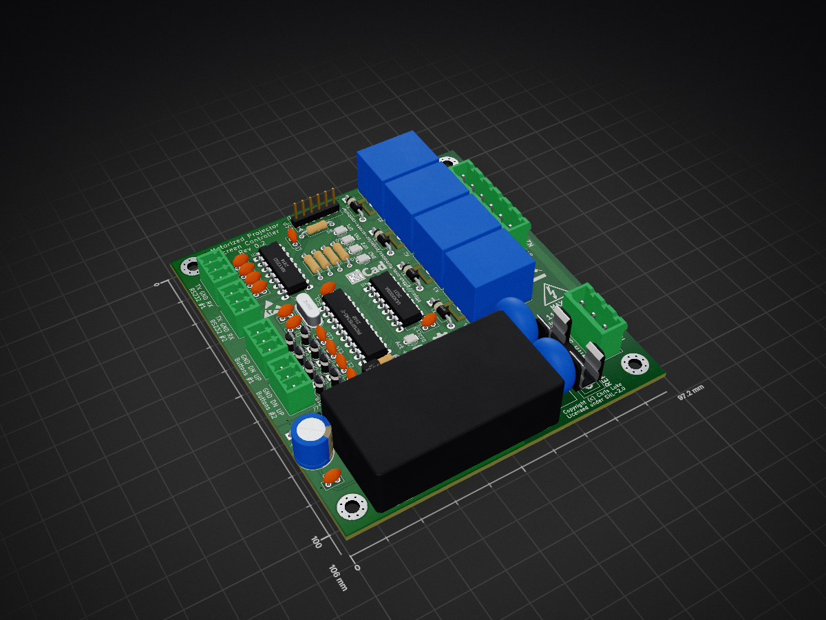
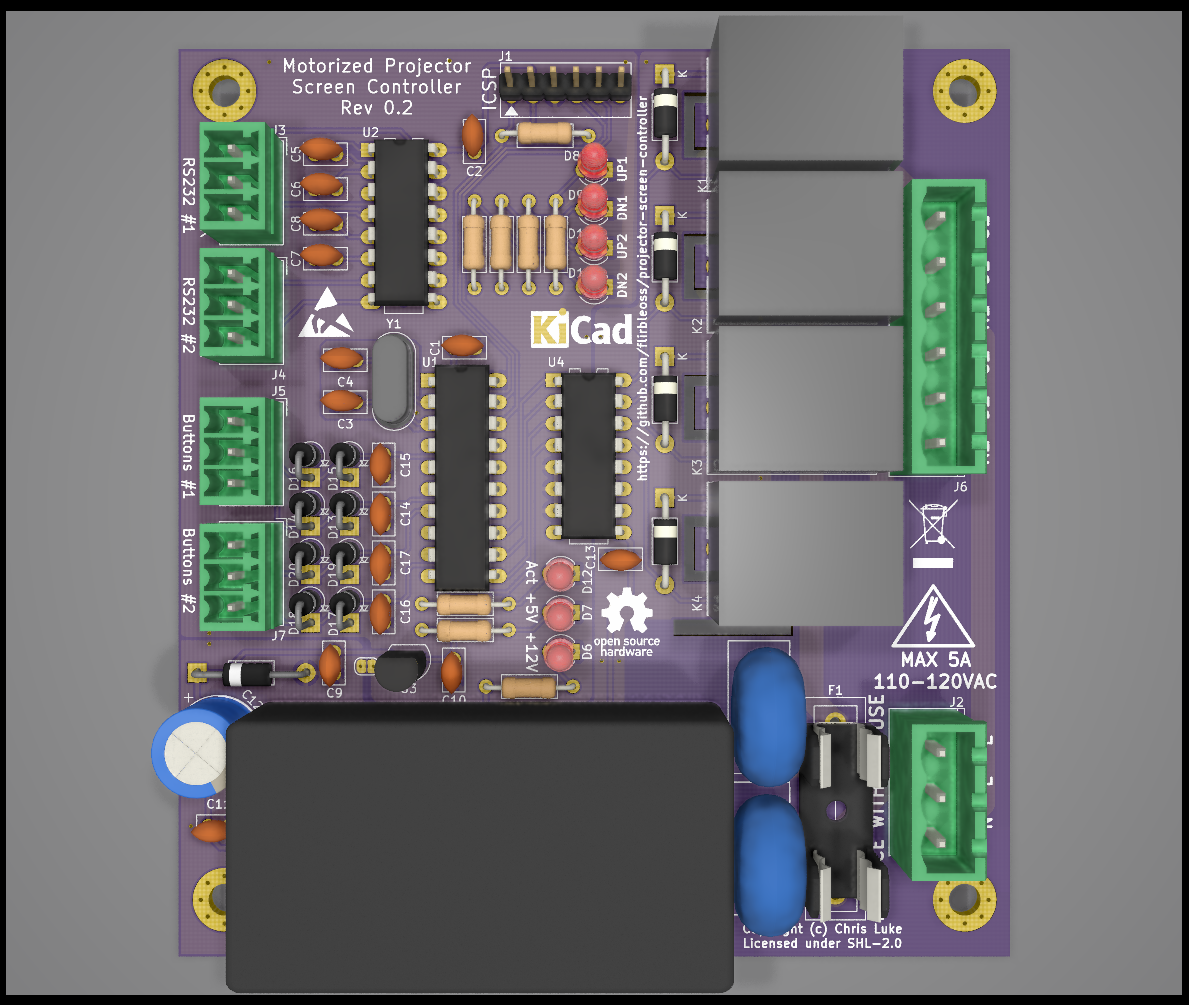
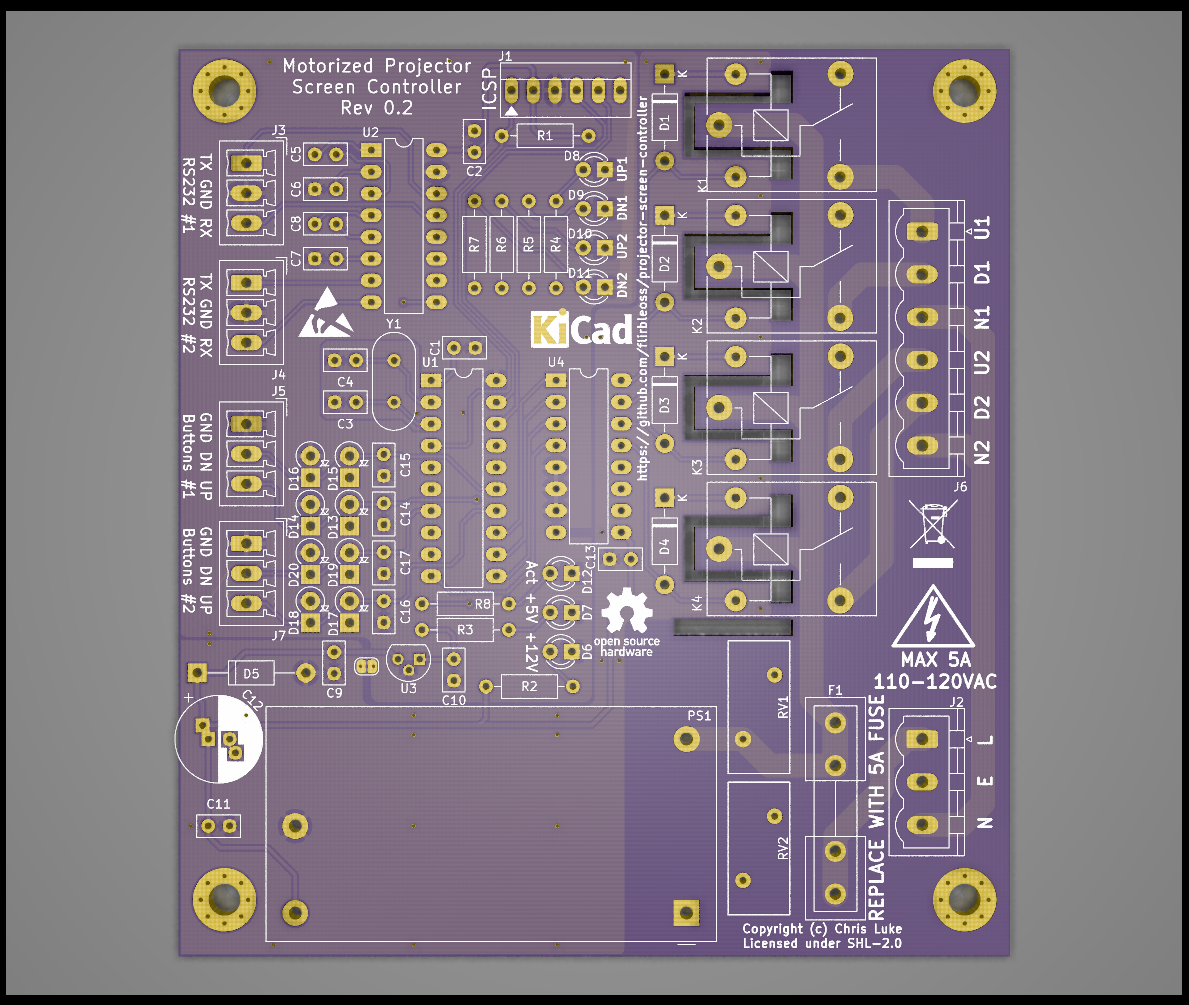
Projector screen controller is an open-source printed circuit board by flirbleoss, from the flirbleoss/projector-screen-controller repository on GitHub. It is a 2-layer board of 97.2 × 106 mm with 75 parts on 61 nets, routed with 467 tracks and 34 vias.
It is built around the PIC16F15345-I/P, MAX232ID and ULN2003A, with the JS1-12V-F among its other parts. Its parts include 20 diodes, 17 capacitors, 8 resistors, 7 connectors and 4 ICs. It belongs with the PIC boards of this library.


Simple controller for basic motorized projector screens. An almost-drop-in replacement for the Da-Lite SCB-100.
Status: Work in progress
Tired of the commercial screen controller letting out its magic smoke every couple of years and not content with the $400 replacement cost, I decided to make my own almost-drop-in replacement with more emphasis on electronic protection than the commercial variant seems to have.
In my analysis of both SCB-100s that failed, it appeared a transient condition upset the MAX232 driver such that it causes a dead-short between the 5v and 0v rails. The charge pump capacitors of the MAX232 chip are adjacent to the ULN2003 relay driver and the 12V decoupling capacitor. The design relies on the diodes in the ULN2003 for back-EMF suppression, which I speculate may not be adequate for the off-brand relays in use in both of my SCB-100s (an online search reveals other specimens have relays from a more reputable brand, however.) Finally, the switching power supply module is soldered to the back of the logic board. While there is a plastic divider between the boards, there is only a few milimeters of space and line voltage spikes may well cause interference; additionally there are several places where line voltage and signal voltage traces come closer than I would be comfortable with.
It is my conclusion therefore that the failures are likely caused by insufficient physical isolation and insufficient transient back-EMF suppression.
| Qty | Value | Footprint | References |
|---|---|---|---|
| 8 | 1N5817 | Diodes_THT:D_DO-41_SOD81_P2.54mm_Vertical_KathodeUp | D13, D14, D15, D16, D17, D18, D19, D20 |
| 7 | LED | LEDs:LED_D3.0mm | D6, D7, D8, D9, D10, D11, D12 |
| 6 | 330R | Resistor_THT:R_Axial_DIN0207_L6.3mm_D2.5mm_P10.16mm_Horizontal | R3, R4, R5, R6, R7, R8 |
| 5 | 1uF | Capacitors_THT:C_Disc_D5.0mm_W2.5mm_P2.50mm | C2, C5, C6, C7, C8 |
| 4 | 0.01uF | Capacitors_THT:C_Disc_D5.0mm_W2.5mm_P2.50mm | C14, C15, C16, C17 |
| 4 | 1N4004 | Diode_THT:D_DO-41_SOD81_P10.16mm_Horizontal | D1, D2, D3, D4 |
| 4 | JS1-12V-F | Relay_THT:Relay_SPDT_SANYOU_SRD_Series_Form_C | K1, K2, K3, K4 |
| 4 | MCV-3-G | Connector_Phoenix_MC:PhoenixContact_MCV_1,5_3-G-3.5_1x03_P3.50mm_Vertical | J3, J4, J5, J7 |
| 4 | MountingHole_Pad | Mounting_Holes:MountingHole_3.7mm_Pad_Via | H1, H2, H3, H4 |
| 3 | 0.1uF | Capacitors_THT:C_Disc_D5.0mm_W2.5mm_P2.50mm | C1, C10, C13 |
| 2 | 33pF | Capacitors_THT:C_Disc_D5.0mm_W2.5mm_P2.50mm | C3, C4 |
| 2 | 360V | Varistors:RV_Disc_D15.5_W7.2_P7.5 | RV1, RV2 |
| 2 | SolderJumper_2_Bridged | Jumper:SolderJumper-2_P1.3mm_Bridged2Bar_RoundedPad1.0x1.5mm | JP1, JP2 |
| 1 | 0.33uF | Capacitors_THT:C_Disc_D5.0mm_W2.5mm_P2.50mm | C9 |
| 1 | 10K | Resistor_THT:R_Axial_DIN0207_L6.3mm_D2.5mm_P10.16mm_Horizontal | R1 |
| 1 | 15V | Diodes_THT:D_DO-41_SOD81_P12.70mm_Horizontal | D5 |
| 1 | 1K | Resistor_THT:R_Axial_DIN0207_L6.3mm_D2.5mm_P10.16mm_Horizontal | R2 |
| 1 | 1uF/25V | Capacitors_THT:C_Disc_D5.0mm_W2.5mm_P2.50mm | C11 |
| 1 | 470uF/25V | Capacitor_THT:CP_Radial_D10.0mm_P2.50mm_P5.00mm | C12 |
| 1 | 5A | Fuse_Holders_and_Fuses:Fuseholder5x20_horiz_open_inline_Type-I | F1 |
| 1 | 8MHz | Crystal:Crystal_HC49-4H_Vertical | Y1 |
| 1 | ICSP | Connectors:PINHEAD1-6 | J1 |
| 1 | L78L05_TO92 | Package_TO_SOT_THT:TO-92L | U3 |
| 1 | MAX232I | Package_DIP:DIP-16_W7.62mm_LongPads | U2 |
| 1 | MSTBVA 2,5 HC/ 3-G | Connector_Phoenix_MSTB:PhoenixContact_MSTBVA_2,5_3-G_1x03_P5.00mm_Vertical | J2 |
| 1 | MSTBVA 2,5/ 6-G | Connector_Phoenix_MSTB:PhoenixContact_MSTBVA_2,5_6-G_1x06_P5.00mm_Vertical | J6 |
| 1 | PIC16F15345-I/P | Package_DIP:DIP-20_W7.62mm_LongPads | U1 |
| 1 | PSK-S20C-12 | Chris_Power:ACDC-Conv_CUI-PSK-S20C | PS1 |
| 1 | ULN2003A | Package_DIP:DIP-16_W7.62mm_LongPads | U4 |
The 71 most common of 75 parts.
It measures 97.2 × 106 mm and has 2 copper layers, 1.6 mm thick.
75 parts, built around the PIC16F15345-I/P, MAX232ID, ULN2003A and JS1-12V-F. The full list of its parts is on this page, with links to each part's symbol and footprint where PCBKit's library has them.
From the flirbleoss/projector-screen-controller repository on GitHub, at the commit this page was made from: the board is board/projector-screen-controller.kicad_pcb. PCBKit opens the board in the browser, with nothing to install.
Its repository states no licence, so its author keeps all rights: ask flirbleoss before reusing the design.

famicomical/MB9X-UART
In-system Serial Programming Adapter for Fujitsu F2MC-16LX microcontrollers


dbalsom/arduinoX86
An interface between an Arduino Due or Arduino GIGA and 8088, 8086, V20, V30, 186 or 286 CPUs

fehlfarbe/arduino-motorfocus
Arduino motorfocus with moonlite protocol for telescopes

Scottapotamas/zaphod-bot
A DIY high performance delta-bot for fun, and lightpainting...

AllYarnsAreBeautiful/ayab-hardware
Contains the schematics and layouts for the AYAB Arduino shield