2 layers99.3 × 78 mm

 flabou/digital_load3
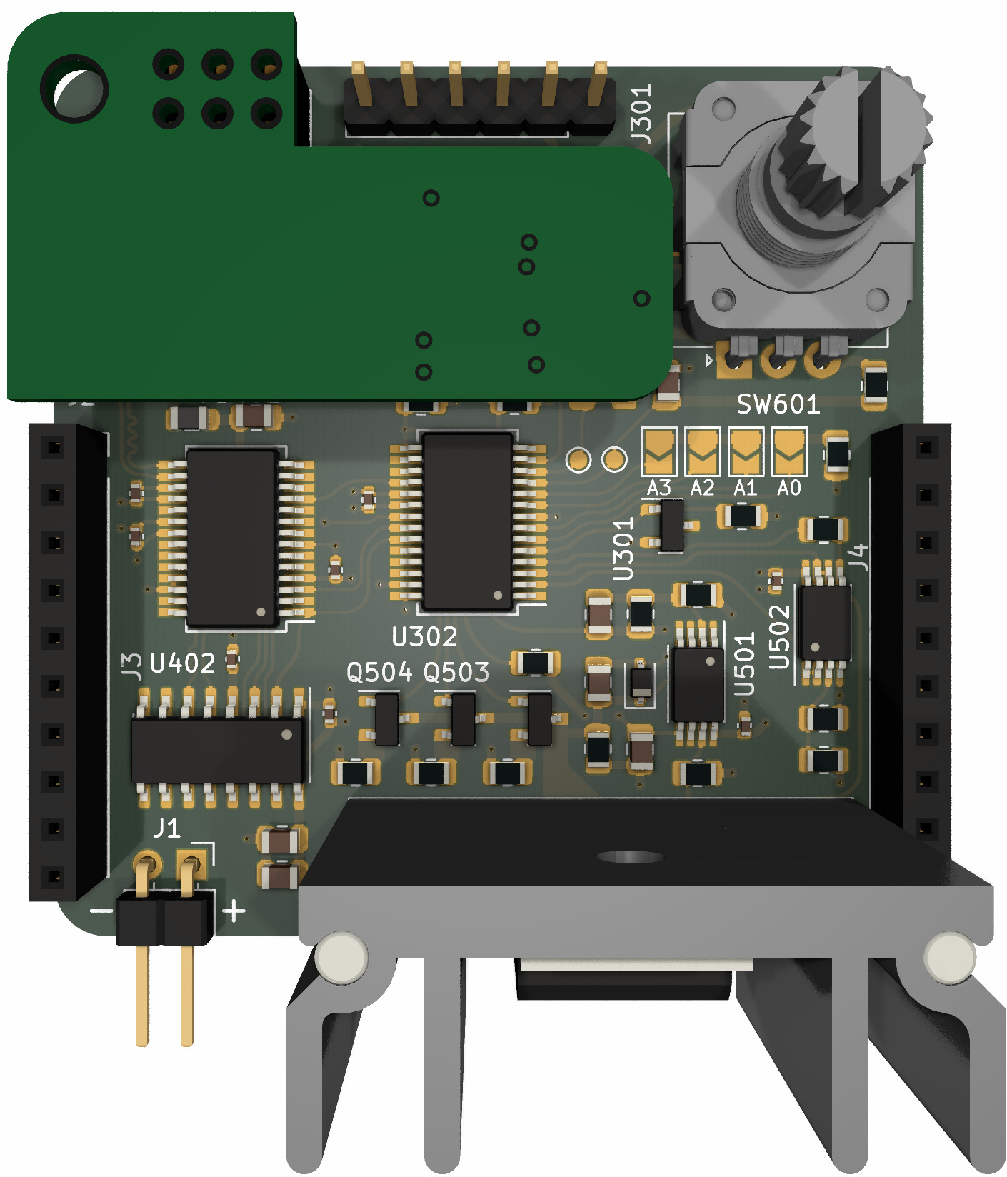
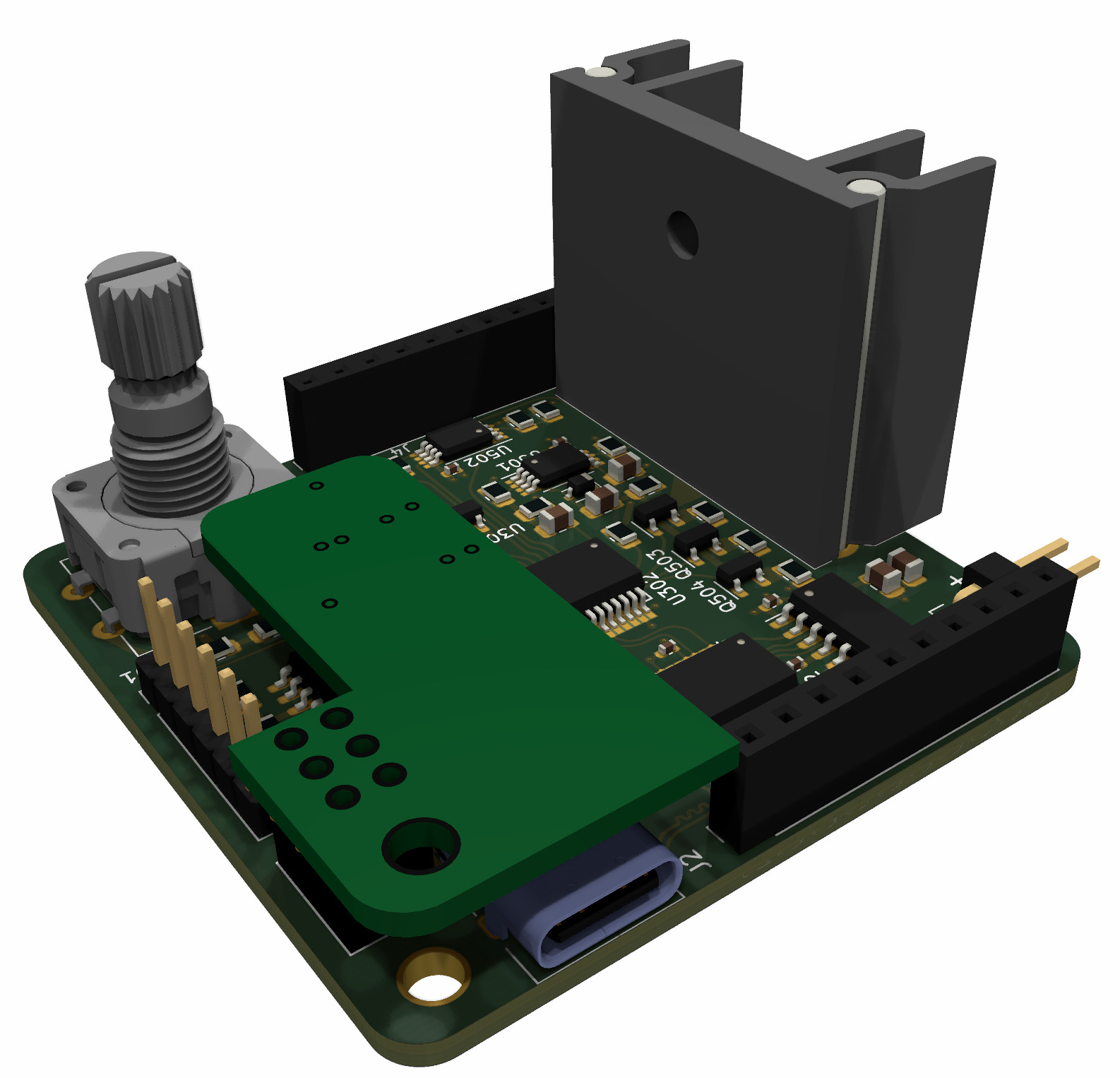
Digital load circuit made in kicad
Digital load rounded is an open-source printed circuit board by flabou, from the flabou/digital_load repository on GitHub, published under the MIT licence. It is a 4-layer board of 50 × 50 mm with 77 parts on 76 nets, routed with 402 tracks and 64 vias.
It is built around the PIC18F24K42-I/MV, LM2904BAID and CH340C, with the FT232RL, IRLS640A and SP0503BAHTG among its other parts. Its parts include 29 resistors, 19 capacitors, 8 ICs, 5 connectors and 4 transistors. It belongs with the PIC boards of this library.


This is a digital load circuit, project is WIP. Intended features are:
| Qty | Value | Footprint | References |
|---|---|---|---|
| 16 | 10k | Resistor_SMD:R_0805_2012Metric | R301, R302, R303, R304, R306, R501, R503, R504, R505, R508, R601, R602, R603, R604, R605, R701 |
| 9 | 100n | Capacitor_SMD:C_0402_1005Metric | C301, C402, C403, C404, C406, C407, C408, C502, C505 |
| 4 | 10n | Capacitor_SMD:C_0805_2012Metric | C503, C504, C601, C602 |
| 4 | 4.7u | Capacitor_SMD:C_0805_2012Metric | C401, C405, C409, C501 |
| 4 | SB | Jumper:SolderJumper-2_P1.3mm_Open_TrianglePad1.0x1.5mm | JP301, JP302, JP303, JP304 |
| 3 | 4.7k | Resistor_SMD:R_0805_2012Metric | R305, R307, R308 |
| 3 | Q_NMOS_GSD | Package_TO_SOT_SMD:SOT-23 | Q502, Q503, Q504 |
| 2 | 1u | Capacitor_SMD:C_0805_2012Metric | C701, C702 |
| 2 | 5.1k | Resistor_SMD:R_0805_2012Metric | R1, R2 |
| 2 | Conn_01x10 | Connector_PinSocket_2.54mm:PinSocket_1x10_P2.54mm_Vertical | J3, J4 |
| 2 | LM2904BA | Package_SO:TSSOP-8_4.4x3mm_P0.65mm | U501, U502 |
| 2 | ~ | TestPoint:TestPoint_Pad_D1.0mm | TP300, TP301 |
| 1 | 1 | Resistor_SMD:R_0805_2012Metric | R510 |
| 1 | 100 | Resistor_SMD:R_0805_2012Metric | R509 |
| 1 | 10m | Resistor_SMD:R_0805_2012Metric | R511 |
| 1 | 120k | Resistor_SMD:R_0805_2012Metric | R703 |
| 1 | 200k | Resistor_SMD:R_0805_2012Metric | R702 |
| 1 | 270k | Resistor_SMD:R_0805_2012Metric | R502 |
| 1 | 4.7M | Resistor_SMD:R_0805_2012Metric | R506 |
| 1 | 47k | Resistor_SMD:R_0805_2012Metric | R507 |
| 1 | Adafruit_PiOLED | 0_Display:PiOLED | U601 |
| 1 | CH340C | Package_SO:SOIC-16_3.9x9.9mm_P1.27mm | U402 |
| 1 | Conn_01x02 | Connector_PinHeader_2.54mm:PinHeader_1x02_P2.54mm_Horizontal | J1 |
| 1 | Conn_PIC_ICSP_ICD | Connector_PinHeader_2.54mm:PinHeader_1x06_P2.54mm_Vertical | J301 |
| 1 | DIODE | Diode_SMD:D_SOD-323 | D501 |
| 1 | FT232RL | Package_SO:SSOP-28_5.3x10.2mm_P0.65mm | U401 |
| 1 | FerriteBead | Inductor_SMD:L_0805_2012Metric | FB401 |
| 1 | Heatsink_Pad | 0_Heatsink:Heatsink_ASSMANN_WSW_V6560W | HS501 |
| 1 | IRLS640A | Package_TO_SOT_THT:TO-220-3_Vertical | Q501 |
| 1 | LM4040DBZ-2.0 | Package_TO_SOT_SMD:SOT-23 | U301 |
| 1 | LP2951-3.3_SOIC | Package_SO:SOIC-8_3.9x4.9mm_P1.27mm | U701 |
| 1 | PEC11R | Rotary_Encoder:RotaryEncoder_Alps_EC12E-Switch_Vertical_H20mm | SW601 |
| 1 | PIC18F24K42 | Package_SO:SSOP-28_5.3x10.2mm_P0.65mm | U302 |
| 1 | SP0503BAHTG | Package_TO_SOT_SMD:SOT-143 | D1 |
| 1 | Thermistor_NTC | Resistor_SMD:R_0402_1005Metric | TH501 |
| 1 | USB_C_Receptacle_USB2.0 | Connector_USB:USB_C_Receptacle_GCT_USB4085 | J2 |
It measures 50 × 50 mm and has 4 copper layers, 1.66 mm thick.
77 parts, built around the PIC18F24K42-I/MV, LM2904BAID, CH340C and FT232RL. The full list of its parts is on this page, with links to each part's symbol and footprint where PCBKit's library has them.
From the flabou/digital_load repository on GitHub, at the commit this page was made from: the board is digital_load-rounded.kicad_pcb and its schematic connectors.kicad_sch. PCBKit opens the board in the browser, with nothing to install.
Its repository publishes it under the MIT licence: you may reuse it on that licence's terms (keep the author's notice, and for a copyleft licence share your changes alike).


reinto1234/H_Bridge_PCB
The project consists of two main components: 1. HBridgePCBDesign — KiCad PCB layout and schematic. 2. HBridgePCBCode — Firmware for the ESP32 controller.

fossasia/pslab-hardware
PSLab Hardware Design and Schematics https://pslab.io


FeralFirmware/TailTalk
A modern async user space AppleTalk stack with Rust + Tokio