2 layers165.1 × 88.9 mm
Display Board
Fish-in-a-Barrel/Nixie
This is my Nixie clock project. It was created as an excuse to learn more about electronics and it touches on power circuits, microcontrollers, serial communications, and more.
45 parts

 Fish-in-a-Barrel/Nixie
This is my Nixie clock project. It was created as an excuse to learn more about electronics and it touches on power circuits, microcontrollers, serial communications, and more.
Clock Controller is an open-source printed circuit board by Fish-in-a-Barrel, from the Fish-in-a-Barrel/Nixie repository on GitHub. It is a 4-layer board of 63.5 × 44.5 mm with 48 parts on 50 nets, routed with 171 tracks and 72 vias.
It is built around the PIC16F15224-I/SL, AS78L05RTR-E1 and MMBT2222A-TP, with the FDD7N25LZTM, MMBT2907ALT1G and PEC11S-929K-S0015 among its other parts. Its parts include 13 resistors, 9 capacitors, 6 transistors, 3 ICs and 2 connectors. It belongs with the lEDs and displays boards and the PIC boards of this library.


https://github.com/user-attachments/assets/0fcae77a-54a8-4b7d-9e90-6edd31807fbd
This is my Nixie clock project. It was created as an excuse to learn more about electronics and it touches on power circuits, microcontrollers, serial communications, and more.
The clock runs 12 IN-12A Nixie tubes that display the time and date. INS-1 tubes are used for digit separators. It also includes:
Hardware: KiCad 8 Firmware: MPLAB X IDE
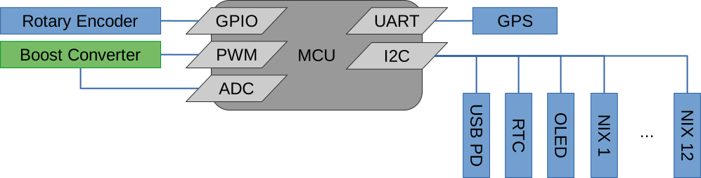
A Microchip PIC16F15224 8-bit microcontroller is the main processing unit of the clock. It controls the boost converter while managing and coordinating the other hardware modules.
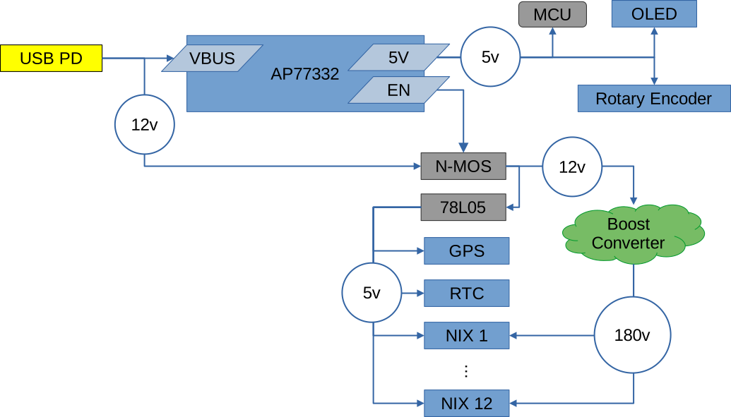
A Diodes Incorporated AP33772 is used to negotiate with a PD source for the input power. The AP33772 is controlled by the main MCU via I2C. The AP33772 requests 12V from the power source, which supplies the boost converter.
The AP33772 also provides a dedicated 5V power source. This is a low current source, so it is only used to drive the MCU and UI, which are needed during power-up. A separate 78L05 regulator (powered by the 12V from USB VBUS) provides 5V power to all of the other devices.
Finally, the AP33772 provides over-current and over-voltage protection features.
A 128x32 OLED display (driven by an SSD1306) is used to display status and diagnostics information. A rotary encoder with detent is used to scroll through the different display pages, and to select timezone and DST support. The OLED pixel data is sent over I2C.
A DS3231 RTC module provides an accurate time source for the clock. It is the source of the time/date displayed and is only updated if it differs from the GPS time. The RTC module is also equiped with a battery backup. This allows the clock to display time/date immediately after power-on instead of having to wait several minutes for valid GPS data. RTC data is sent over I2C.
The U-Blox NEO-6M GPS module provides a reference time to initialize the RTC. The module streams standard NMEA messages to the primary MCU over UART serial. Time/date are decoded from these messages.
Each Nixie tube has a driver board. This board has a Microchip PIC16F15243 MCU in I2C client mode receiving commands from the primary MCU. This client MCU drives the Nixie pins and provides features such as digit cross-fading and cathode maintenance.
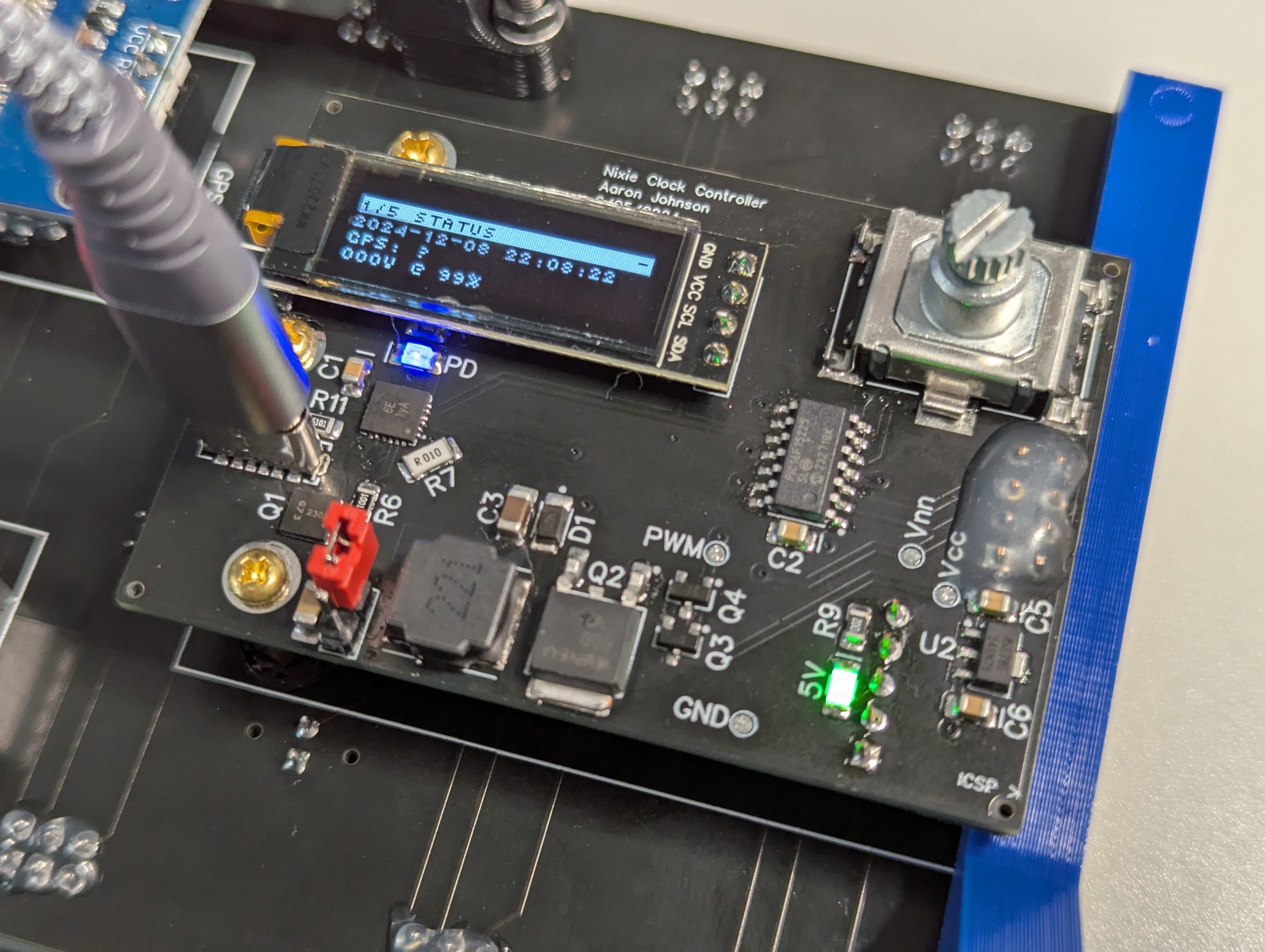
This is the main controller board. It connects to a header on the back of the display board and has these main components:
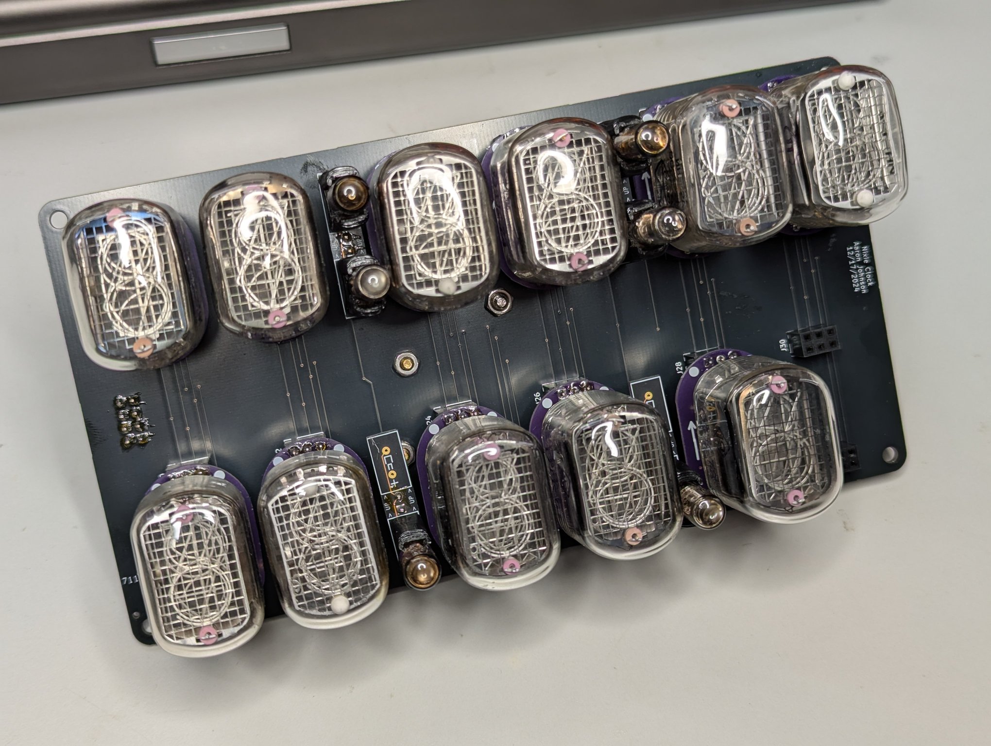
This board servers as the main support structure of the clock. The Nixie drivers connect to headers on the front of the board. The controller board, GPS, and RTC all connect to the back of the board.
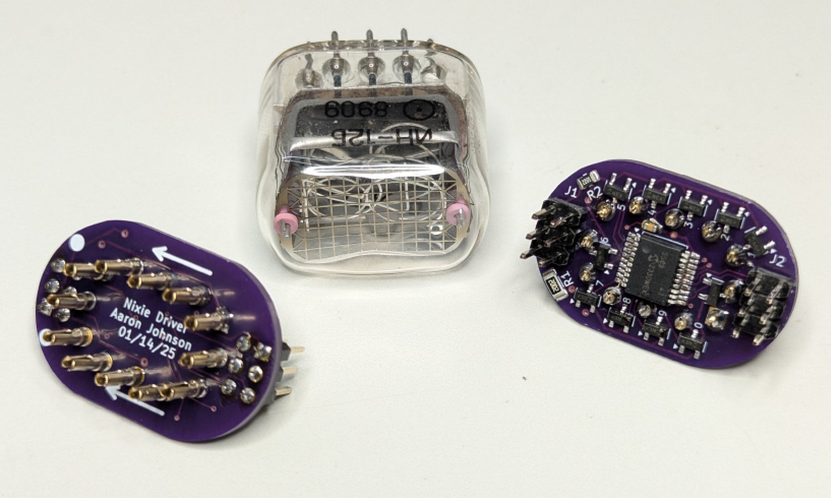
The driver board for each individual IN-12 Nixie tube.
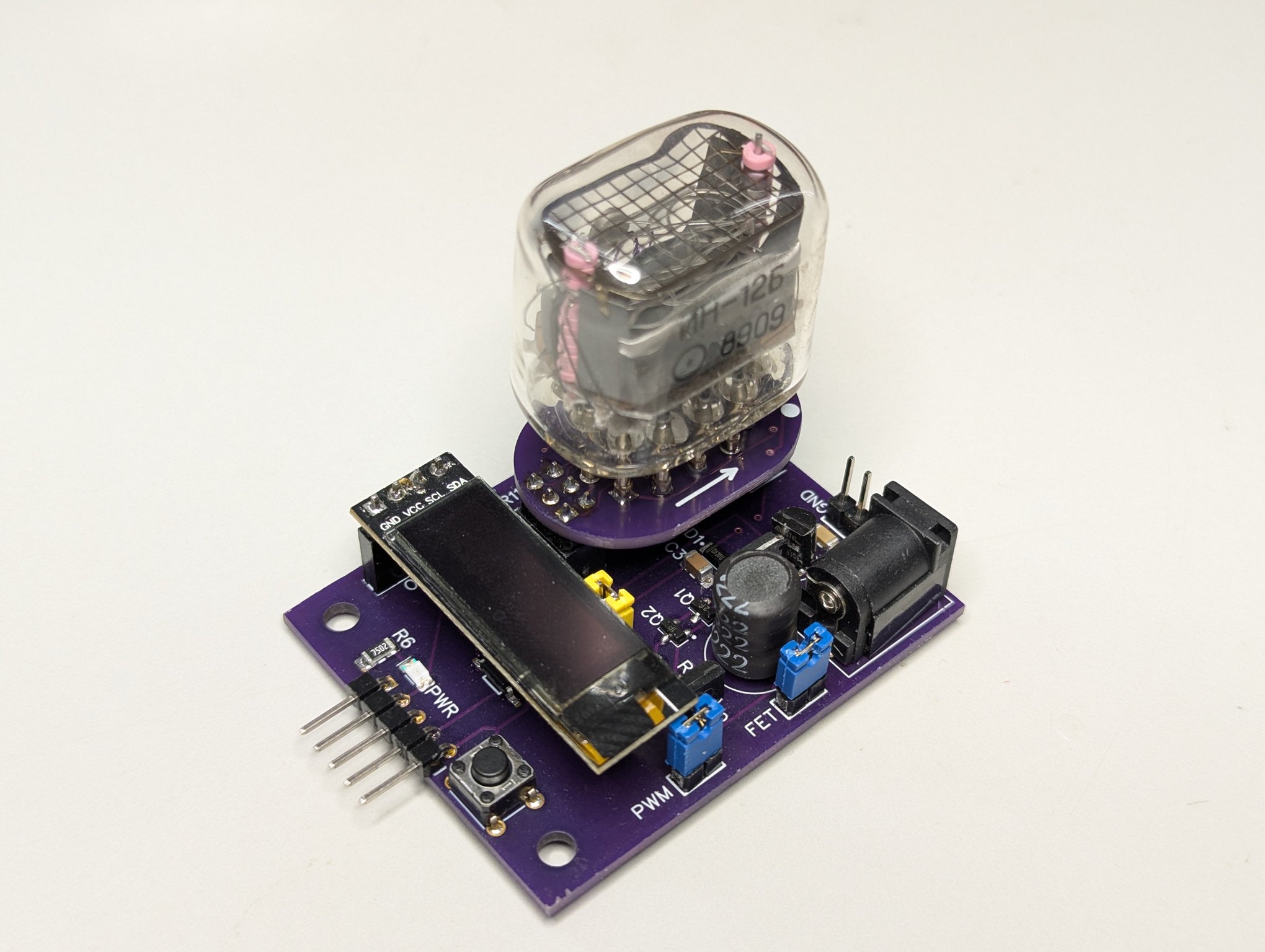
This is a stand-alone test board that will power and exercise a single NixieDriver and tube. It is used for QA of assembled driver boards and testing of the NixieDriver firmware.
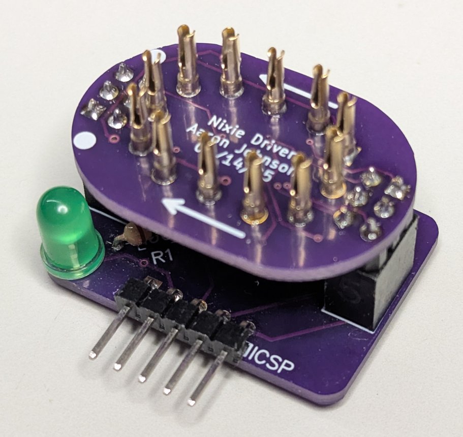
A small board that attaches to a NixieDriver and provides a pin-out compatible with a PICKIT 5 programmer for In Circuit Serial Programming.
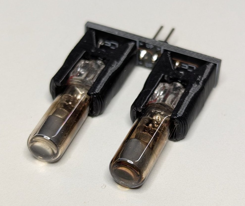
A tiny board that adapts the physical interface of the INS-1 tubes used as digit separators.
| Qty | Value | Footprint | References |
|---|---|---|---|
| 5 | 10k | Resistor_SMD:R_0603_1608Metric | R5, R8, R9, R12, R13 |
| 4 | 100nF | Capacitor_SMD:C_0805_2012Metric | C1, C2, C5, C6 |
| 4 | Most Density | Clock Controller:TP_1.25MM | GND0, PWM0, Vcc0, Vnn0 |
| 3 | 10nF | Capacitor_SMD:C_0603_1608Metric | C7, C8, C9 |
| 3 | M2.5_MTGP540H285 | Clock Controller:M2.5_MTGP540H285 | MH1, MH2, MH3 |
| 3 | MMBT2222A-TP | Package_TO_SOT_SMD:SOT-23 | Q3, Q5, Q6 |
| 2 | 2.2k | Resistor_SMD:R_0603_1608Metric | R1, R2 |
| 2 | 5.1k | Resistor_SMD:R_0603_1608Metric | R10, R11 |
| 1 | 0.01 | Resistor_SMD:R_1206_3216Metric | R7 |
| 1 | 10uF | Capacitor_SMD:C_1812_4532Metric | C3 |
| 1 | 12k | Resistor_SMD:R_0805_2012Metric | R4 |
| 1 | 1k | Resistor_SMD:R_0805_2012Metric | R6 |
| 1 | 1uF | Capacitor_SMD:C_1206_3216Metric | C4 |
| 1 | 220uH | Clock Controller:SRN8040TA221M | L1 |
| 1 | 750k | Resistor_SMD:R_0805_2012Metric | R3 |
| 1 | AP33772DKZ-13 | Package_DFN_QFN:QFN-24-1EP_4x4mm_P0.5mm_EP2.7x2.7mm | U4 |
| 1 | AS78L05RTR-E1 | Package_TO_SOT_SMD:SOT-89-3 | U2 |
| 1 | DMG7430LFG-7 | Diodes Incorporated:PowerDI3333-8 | Q1 |
| 1 | FDD7N25LZTM | Package_TO_SOT_SMD:TO-252-2 | Q2 |
| 1 | HDR-1X2H | Connector_PinHeader_2.54mm:PinHeader_1x02_P2.54mm_Horizontal | J2 |
| 1 | HDR-1X4 | Display_:SSD1306 0.91 128x32 OLED | OLED0 |
| 1 | HDR-2X4 | Connector_PinHeader_2.54mm:PinHeader_2x04_P2.54mm_Vertical | DISP0 |
| 1 | LED_1206(3216_METRIC)_N_BLUE | LED_SMD:LED_1206_3216Metric | PD0 |
| 1 | LED_1206(3216_METRIC)_N_GREEN | LED_SMD:LED_1206_3216Metric | UNK5V0 |
| 1 | MMBT2907ALT1G | Package_TO_SOT_SMD:SOT-23 | Q4 |
| 1 | PEC11S-929K-S0015 | Rotary_Encoder_:PEC11S-929K-S0015 | S1 |
| 1 | PIC16F15224-I/SL | Clock Controller:SOIC14P127_869X599X175L84X42N | U1 |
| 1 | PPPC051LGBN-RC | Connector_PinSocket_2.54mm:PinSocket_1x05_P2.54mm_Horizontal | ICSP0 |
| 1 | SMD220PL | Diode_SMD:D_SOD-123F | D1 |
| 1 | UJC-VP-3-SMT-TR | Connector USB:CUI_UJC-VP-3-SMT-TR | J1 |
It measures 63.5 × 44.5 mm and has 4 copper layers, 1.6 mm thick.
48 parts, built around the PIC16F15224-I/SL, AS78L05RTR-E1, MMBT2222A-TP and FDD7N25LZTM. The full list of its parts is on this page, with links to each part's symbol and footprint where PCBKit's library has them.
From the Fish-in-a-Barrel/Nixie repository on GitHub, at the commit this page was made from: the board is ClockController.X/Hardware/Clock Controller.kicad_pcb and its schematic ClockController.X/Hardware/+5 VRC.kicad_sch. PCBKit opens the board in the browser, with nothing to install.
Its repository states no licence, so its author keeps all rights: ask Fish-in-a-Barrel before reusing the design.
Fish-in-a-Barrel/Nixie
This is my Nixie clock project. It was created as an excuse to learn more about electronics and it touches on power circuits, microcontrollers, serial communications, and more.

Fish-in-a-Barrel/Nixie
This is my Nixie clock project. It was created as an excuse to learn more about electronics and it touches on power circuits, microcontrollers, serial communications, and more.

Fish-in-a-Barrel/Nixie
This is my Nixie clock project. It was created as an excuse to learn more about electronics and it touches on power circuits, microcontrollers, serial communications, and more.

Fish-in-a-Barrel/Nixie
This is my Nixie clock project. It was created as an excuse to learn more about electronics and it touches on power circuits, microcontrollers, serial communications, and more.


Enthusela/DesktopControlPanel
An open-source, hand-built, tactile, home-brew smart-home hub with analog PC audio monitoring and control.


jimahlstrom/HL2IOBoard
A PCB added to the HL2 with IO resources to control filters and antennas

PubInv/general-purpose-alarm-device
A general purpose alarm device (with software) as a module for medical devices (and others)

Konkzor/LinKey
Une clé WIFI lisant la sortie TIC du Linky connectée au broker MQTT d'un Home Assistant


mlh5599/FanPWMtoRotorLock
Converts the output from a 12v PWM fan to a rotor lock detector signal