4 layers170 × 100 mm

 FirstTestStation/Selftest_Board
KiCad PCB design utilized in the creation of the Selftest Board.
Selftest bd is an open-source printed circuit board by FirstTestStation, from the FirstTestStation/Selftest_Board repository on GitHub, published under the CERN-OHL-W-2.0 licence. It is a 4-layer board of 300 × 150 mm with 508 parts on 636 nets, routed with 2,810 tracks and 32 vias.
It is built around the DS2431P+, ULN2003A and 9001-14961C00A. Its parts include 17 switches, 16 resistors, 5 diodes, 4 ICs and 4 connectors.


This project involves the assembly of a custom Selftest Circuit Board (PCB) designed to be part of the First TestStation project (FTS).
The primary goal of the selftest board is to provide the necessary electronics and multiple connections to validate the Interconnect IO Box.
Due to minor additions, the Selftest Board Assembly has been updated to become the Selftest Box Assembly. The documentation for these updates has been included in the same repository.
This section contains the materials and instructions required to assemble the Selftest Board.
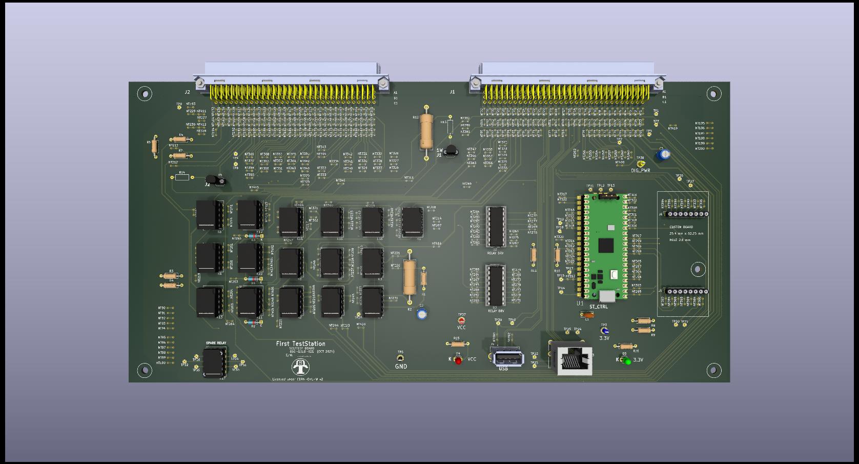
Follow the document Assembly_Instructions to complete the assembly of the board.
This project is licensed under the terms of the CERN Open Hardware Licence Version 2 - Weakly Reciprocal (CERN-OHL-W 2.0).
See the LICENSE file in this repository for more details.
For any issues or further questions, feel free to contact me at [daniellockhead@gmail.com] or open an issue on GitHub.
| Qty | Value | Footprint | References |
|---|---|---|---|
| 17 | TQ2-5_Split | Selftest:Relay_DPDT_FRT5 | K1, K2, K3, K4, K5, K6, K7, K8, K10, K11, K12, K13, K14, K15, K16, K17 +1 |
| 6 | TestPoint_Small | Selftest:TestPoint_THTPad_D1.5mm_Drill0.7mm | TP22, TP23, TP24, TP25, TP26, TP27 |
| 4 | 10K | Selftest:R_Axial_DIN0207_L6.3mm_D2.5mm_P10.16mm_Horizontal | R3, R4, R10, R11 |
| 3 | 1N4148 | Selftest:D_DO-35_SOD27_P7.62mm_Horizontal | D1, D2, D3 |
| 2 | 10 | Selftest:R_Axial_DIN0617_L17.0mm_D6.0mm_P25.40mm_Horizontal | R2, R12 |
| 2 | 10uF | Selftest:CP_Radial_Tantal_D4.5mm_P2.50mm | C2, C3 |
| 2 | 4.7 | Selftest:R_Axial_DIN0207_L6.3mm_D2.5mm_P10.16mm_Horizontal | R5, R7 |
| 2 | 4.7K | Selftest:R_Axial_DIN0207_L6.3mm_D2.5mm_P10.16mm_Horizontal | R8, R9 |
| 2 | 8 x 2.54mm | Selftest:PinSocket_1x08_P2.54mm_Vertical | J5, J6 |
| 2 | 9001-14961C00A | Selftest:900114961C00A | J1, J2 |
| 2 | DS2431 | Selftest:TO-92_Inline_Wide | U4, U5 |
| 2 | LED | Selftest:LED_D3.0mm | D4, D5 |
| 2 | LOGO | LOGO | G***, G*** |
| 2 | N.A | Selftest:R_Axial_DIN0207_L6.3mm_D2.5mm_P10.16mm_Horizontal | R13, R14 |
| 2 | ULN2003A | Selftest:DIP-16_W7.62mm_LongPads | U2, U3 |
| 2 | VM_I | Selftest:NetTie-2_Front1.0mm | NT194, NT245 |
| 2 | VM_L | Selftest:NetTie-2_Front1.0mm | NT128, NT202 |
| 1 | 0.1uF | Selftest:C_Disc_D6.0mm_W2.5mm_P5.00mm | C1 |
| 1 | 10 | Selftest:R_Axial_DIN0207_L6.3mm_D2.5mm_P10.16mm_Horizontal | R6 |
| 1 | 100 | Selftest:R_Axial_DIN0207_L6.3mm_D2.5mm_P10.16mm_Horizontal | R1 |
| 1 | 100R | Selftest:NetTie-2_Front1.0mm | NT220 |
| 1 | 10B_NC | Selftest:NetTie-2_Front1.0mm | NT401 |
| 1 | 10B_NO | Selftest:NetTie-2_Front1.0mm | NT402 |
| 1 | 10C_NC | Selftest:NetTie-2_Front1.0mm | NT403 |
| 1 | 10C_NO | Selftest:NetTie-2_Front1.0mm | NT404 |
| 1 | 10R | Selftest:NetTie-2_Front1.0mm | NT221 |
| 1 | 11B_NC | Selftest:NetTie-2_Front1.0mm | NT405 |
| 1 | 11B_NO | Selftest:NetTie-2_Front1.0mm | NT406 |
| 1 | 11C_NC | Selftest:NetTie-2_Front1.0mm | NT407 |
| 1 | 11C_NO | Selftest:NetTie-2_Front1.0mm | NT408 |
| 1 | 12B_NC | Selftest:NetTie-2_Front1.0mm | NT414 |
| 1 | 12B_NO | Selftest:NetTie-2_Front1.0mm | NT415 |
| 1 | 12C_NC | Selftest:NetTie-2_Front1.0mm | NT416 |
| 1 | 12C_NO | Selftest:NetTie-2_Front1.0mm | NT417 |
| 1 | 13_NC | Selftest:NetTie-2_Front1.0mm | NT219 |
| 1 | 13_W | Selftest:NetTie-2_Front1.0mm | NT213 |
| 1 | 14B_NC | Selftest:NetTie-2_Front1.0mm | NT217 |
| 1 | 14B_NO | Selftest:NetTie-2_Front1.0mm | NT218 |
| 1 | 14B_W | Selftest:NetTie-2_Front1.0mm | NT222 |
| 1 | 15B_NC | Selftest:NetTie-2_Front1.0mm | NT232 |
| 1 | 15B_NO | Selftest:NetTie-2_Front1.0mm | NT233 |
| 1 | 15C_NO | Selftest:NetTie-2_Front1.0mm | NT243 |
| 1 | 16B_NC | Selftest:NetTie-2_Front1.0mm | NT239 |
| 1 | 16B_NO | Selftest:NetTie-2_Front1.0mm | NT240 |
| 1 | 16C_NC | Selftest:NetTie-2_Front1.0mm | NT241 |
| 1 | 16C_NO | Selftest:NetTie-2_Front1.0mm | NT242 |
| 1 | 17AC | Selftest:TestPoint_THTPad_D1.5mm_Drill0.7mm | TP31 |
| 1 | 17AN0 | Selftest:TestPoint_THTPad_D1.5mm_Drill0.7mm | TP34 |
| 1 | 17ANC | Selftest:TestPoint_THTPad_D1.5mm_Drill0.7mm | TP33 |
| 1 | 17BC | Selftest:TestPoint_THTPad_D1.5mm_Drill0.7mm | TP32 |
| 1 | 17BN0 | Selftest:TestPoint_THTPad_D1.5mm_Drill0.7mm | TP36 |
| 1 | 17BNC | Selftest:TestPoint_THTPad_D1.5mm_Drill0.7mm | TP35 |
| 1 | 2C_NC | Selftest:NetTie-2_Front1.0mm | NT225 |
| 1 | 2C_NO | Selftest:NetTie-2_Front1.0mm | NT226 |
| 1 | 2R | Selftest:NetTie-2_Front1.0mm | NT231 |
| 1 | 330 | Selftest:R_Axial_DIN0207_L6.3mm_D2.5mm_P10.16mm_Horizontal | R16 |
| 1 | 3V3_TESTPOINT | Selftest:TestPoint_Loop_D2.54mm_Drill1.5mm_Beaded | TP3 |
| 1 | 470 | Selftest:R_Axial_DIN0207_L6.3mm_D2.5mm_P10.16mm_Horizontal | R15 |
| 1 | 4BNC | Selftest:TestPoint_THTPad_D1.5mm_Drill0.7mm | TP28 |
| 1 | 5D | Selftest:NetTie-2_Front1.0mm | NT216 |
| 1 | 5PWR | Selftest:NetTie-2_Front1.0mm | NT205 |
| 1 | 7B_NC | Selftest:NetTie-2_Front1.0mm | NT237 |
| 1 | 7B_NO | Selftest:NetTie-2_Front1.0mm | NT238 |
| 1 | 7C_NC | Selftest:NetTie-2_Front1.0mm | NT235 |
| 1 | 7C_NO | Selftest:NetTie-2_Front1.0mm | NT236 |
| 1 | 8B_NC | Selftest:NetTie-2_Front1.0mm | NT246 |
| 1 | 8B_NO | Selftest:NetTie-2_Front1.0mm | NT247 |
| 1 | 8C_NC | Selftest:NetTie-2_Front1.0mm | NT248 |
| 1 | 8C_NO | Selftest:NetTie-2_Front1.0mm | NT249 |
| 1 | 9B_NC | Selftest:NetTie-2_Front1.0mm | NT250 |
| 1 | 9B_NO | Selftest:NetTie-2_Front1.0mm | NT251 |
| 1 | 9C_NC | Selftest:NetTie-2_Front1.0mm | NT252 |
| 1 | 9C_NO | Selftest:NetTie-2_Front1.0mm | NT253 |
| 1 | ADC0 | Selftest:NetTie-2_Front1.0mm | NT203 |
| 1 | ADC1 | Selftest:NetTie-2_Front1.0mm | NT204 |
| 1 | AGND | Selftest:NetTie-2_Front1.0mm | NT324 |
| 1 | AWGL | Selftest:NetTie-2_Front1.0mm | NT227 |
| 1 | B12_0H | Selftest:NetTie-2_Front1.0mm | NT326 |
| 1 | B12_0L | Selftest:NetTie-2_Front1.0mm | NT337 |
| 1 | B12_1H | Selftest:NetTie-2_Front1.0mm | NT327 |
The 119 most common of 508 parts.
It measures 300 × 150 mm and has 4 copper layers, 1.6 mm thick.
508 parts, built around the DS2431P+, ULN2003A and 9001-14961C00A. The full list of its parts is on this page, with links to each part's symbol and footprint where PCBKit's library has them.
From the FirstTestStation/Selftest_Board repository on GitHub, at the commit this page was made from: the board is selftest_bd/selftest_bd.kicad_pcb and its schematic selftest_bd/connector.kicad_sch. PCBKit opens the board in the browser, with nothing to install.
Its repository publishes it under the CERN-OHL-W-2.0 licence: you may reuse it on that licence's terms (keep the author's notice, and for a copyleft licence share your changes alike).


Smoothieware/Smoothieboard2
Hardware files for the Smoothieboard v2, and extension boards


dbalsom/arduinoX86
An interface between an Arduino Due or Arduino GIGA and 8088, 8086, V20, V30, 186 or 286 CPUs

fehlfarbe/arduino-motorfocus
Arduino motorfocus with moonlite protocol for telescopes

Scottapotamas/zaphod-bot
A DIY high performance delta-bot for fun, and lightpainting...