2 layers106.7 × 36 mm

 FinnKrieger/dashbox-pcb
A two-layer dashboard controller board for the USC Formula Electric car. It sits on the vehicle CAN bus, drives the driver-facing dash, and takes its power from the car's 12 V rail.
Dashbox is an open-source printed circuit board by FinnKrieger, from the FinnKrieger/dashbox-pcb repository on GitHub, published under the MIT licence. It is a 2-layer board of 71.5 × 66 mm with 38 parts on 52 nets, routed with 272 tracks and 20 vias.
It is built around the SN65HVD230D, AMS1117-3.3 and AO3400A, with the ACT1210-101-2P-TL00, ESD2CANFD24DBZRQ1 and GZ1608D601TF among its other parts. Its parts include 13 resistors, 10 capacitors, 4 connectors, 3 ICs and 3 transistors. It belongs with the STM32 boards of this library.


A two-layer dashboard controller board for the USC Formula Electric car. It sits on the vehicle CAN bus, drives the driver-facing dash, and takes its power from the car's 12 V rail.
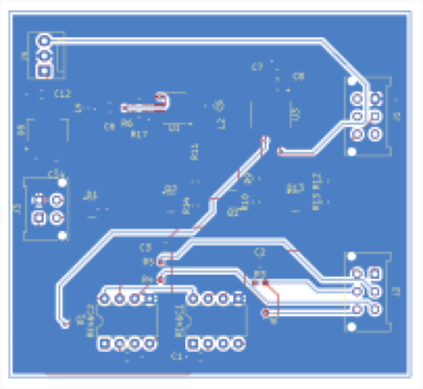
Front and back copper with silkscreen and board outline, as of the final revision.
| MCU | STM32C011F4Px |
| Bus | CAN via SN65HVD230 transceiver |
| Bus protection | ESD2CANFD24DBZRQ1, ACT1210-101 common-mode choke |
| Power | AMS1117-3.3 LDO from vehicle 12 V |
| Switching | AO3400A N-channel MOSFETs (×3) |
| Layers | 2 (F.Cu / B.Cu), 1.6 mm |
| Footprints | 38 |
| Routing | 272 track segments, 20 vias, ground pour |
The CAN front end carries the parts you would expect on a vehicle bus that runs next to a tractive system: a common-mode choke and a dedicated ESD device ahead of the transceiver, with a ferrite bead on the supply. Connector pinouts are broken out to 4- and 6-pin headers for the dash harness.
hardware/
  dashbox.kicad_sch     schematic
  dashbox.kicad_pcb     board layout
  dashbox.kicad_pro     project file
  schematic.pdf         rendered schematic
media/
  layout.png            both copper layers with silkscreen
  layout-top.png        front copper only
Open hardware/dashbox.kicad_pro in KiCad 9.0 or later.
The commit history reconstructs the design's real progression from dated KiCad save snapshots, from the first schematic on 22 September 2025 through the final layout revision on 19 November 2025. Each commit corresponds to an actual working session.
The largest single change was on 22 October, when copper pours went in and routing was completed; the following week consolidated those pours down to a single ground zone and removed redundant parts.
The Dashbox was designed by Finn Krieger and Aagam (@aagamjai-jpg) for USC Formula Electric.
The car's full electrical system — including the boards this one talks to on the CAN bus — lives in the team repository at SCFormulaElectric/USC-Electrical-Systems, which is the authoritative source for the vehicle design. This repository is a standalone copy of the Dashbox portion, published for portfolio purposes.
Other boards in the vehicle (relay board, precharge, SDC, VIL, RML) are the work of other team members and are not included here.
Released under the MIT License — see LICENSE.
| Qty | Value | Footprint | References |
|---|---|---|---|
| 3 | 12k | Resistor_SMD:R_0603_1608Metric_Pad0.98x0.95mm_HandSolder | R10, R13, R14 |
| 3 | 3k | Resistor_SMD:R_0603_1608Metric_Pad0.98x0.95mm_HandSolder | R9, R11, R12 |
| 3 | AO3400A | Package_TO_SOT_SMD:SOT-23 | Q1, Q2, Q13 |
| 2 | 1.5M | Resistor_SMD:R_0603_1608Metric_Pad0.98x0.95mm_HandSolder | R2, R4 |
| 2 | 10uF | Capacitor_SMD:C_0805_2012Metric_Pad1.18x1.45mm_HandSolder | C5, C14 |
| 2 | 1200pF | Capacitor_SMD:C_0805_2012Metric_Pad1.18x1.45mm_HandSolder | C2, C3 |
| 2 | 150k | Resistor_SMD:R_0603_1608Metric_Pad0.98x0.95mm_HandSolder | R3, R5 |
| 2 | 1uF/50V | Capacitor_SMD:C_0805_2012Metric_Pad1.18x1.45mm_HandSolder | C1, C4 |
| 2 | 60 | Resistor_SMD:R_0603_1608Metric_Pad0.98x0.95mm_HandSolder | R6, R17 |
| 2 | Conn_01x06_Pin | Connector_Molex:Molex_Micro-Fit_3.0_43045-0612_2x03_P3.00mm_Vertical | J1, J2 |
| 2 | ~ | Package_DIP:DIP-8_W7.62mm | RE46C1, RE46C2 |
| 1 | 100nF | Capacitor_SMD:C_0805_2012Metric_Pad1.18x1.45mm_HandSolder | C7 |
| 1 | 10K | Resistor_SMD:R_0603_1608Metric_Pad0.98x0.95mm_HandSolder | R1 |
| 1 | 22uF | Capacitor_SMD:C_0805_2012Metric_Pad1.18x1.45mm_HandSolder | C12 |
| 1 | 4.7nF | Capacitor_SMD:C_0805_2012Metric_Pad1.18x1.45mm_HandSolder | C6 |
| 1 | 4.7uF | Capacitor_SMD:C_0805_2012Metric_Pad1.18x1.45mm_HandSolder | C8 |
| 1 | ACT1210-101-2P-TL00 | Inductor_SMD:L_0603_1608Metric_Pad1.05x0.95mm_HandSolder | L4 |
| 1 | AMS1117-3.3 | Package_TO_SOT_SMD:SOT-223-3_TabPin2 | U6 |
| 1 | Conn_01x04_Pin | Connector_Molex:Molex_Micro-Fit_3.0_43045-0412_2x02_P3.00mm_Vertical | J3 |
| 1 | Conn_01x04_Pin | Connector:FanPinHeader_1x03_P2.54mm_Vertical | J4 |
| 1 | ESD2CANFD24DBZRQ1 | Package_TO_SOT_SMD:SOT-23 | D1 |
| 1 | GZ1608D601TF | Inductor_SMD:L_0603_1608Metric_Pad1.05x0.95mm_HandSolder | L2 |
| 1 | SN65HVD230 | Package_SO:SOIC-8_3.9x4.9mm_P1.27mm | U1 |
| 1 | STM32C011F4Px | Package_SO:TSSOP-20_4.4x6.5mm_P0.65mm | U3 |
It measures 71.5 × 66 mm and has 2 copper layers, 1.6 mm thick.
38 parts, built around the SN65HVD230D, AMS1117-3.3, AO3400A and ACT1210-101-2P-TL00. The full list of its parts is on this page, with links to each part's symbol and footprint where PCBKit's library has them.
From the FinnKrieger/dashbox-pcb repository on GitHub, at the commit this page was made from: the board is hardware/dashbox.kicad_pcb and its schematic hardware/dashbox.kicad_sch. PCBKit opens the board in the browser, with nothing to install.
Its repository publishes it under the MIT licence: you may reuse it on that licence's terms (keep the author's notice, and for a copyleft licence share your changes alike).

Ekta-Gupta27/custom-flight-controller-pcb
Custom flight controller PCB designed in KiCad with STM32F7, multiple sensors, CAN, USB, telemetry, PWM and IO interfaces.


gustebeast/public-steel-guitar
A pedal steel guitar you can build yourself, from parts anyone can buy.

avlyubimov/svc-platform
Status: EVT-LAYOUT-AUTHORIZED; connectivity routing complete; fab review open

mauro-starspec/Elevation_Pivot_Daughter-Board
KiCad 9 daughter board for the Starspec elevation/pivot controller.

rkhvrnen/UDS-logger
A Python script and MCU source code for collecting real-time diagnostic data from control units of a vehicle using UDS over CAN bus.
