

2 layers57.3 × 19 mm

adjustable source for voltages between 0 and 1000V
Hbruecke is an open-source printed circuit board by Fersaar, from the Fersaar/adjustable_high_voltage_source repository on GitHub, published under the GPL-3.0 licence. It is a 2-layer board of 91.4 × 71.1 mm with 26 parts on 18 nets, routed with 136 tracks and 3 vias.
It is built around the FAN73912MX. Its parts include 9 connectors, 6 resistors, 3 capacitors, 2 transistors and 1 IC.
This project was developed as part of the contactless electrostatic grippers project. To control the individual gripper zones, it is essential to supply them with a variable voltage ranging from 0V to 1000V. The required current is minimal, as only the individual gripper electrodes need to be charged. In the final gripper design, this circuit will be positioned between the microcontroller and the gripper.
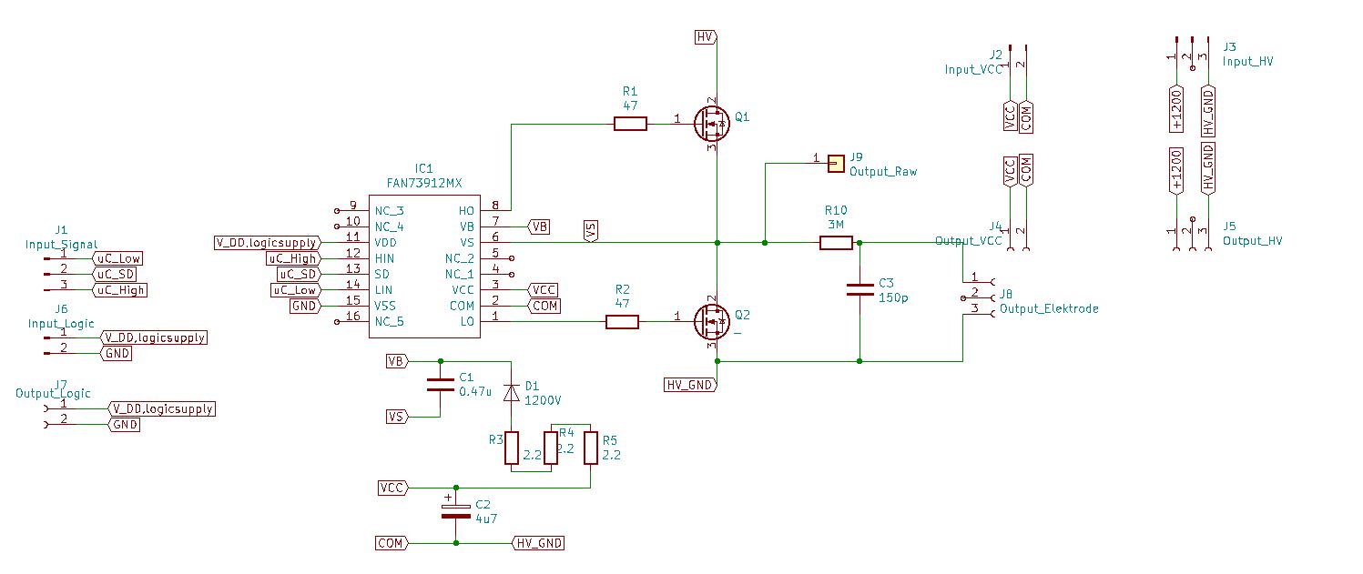
The core of the design is a half-bridge circuit utilizing the "FAN73912mx" driver, which can withstand voltages up to 1200V. However, it is not isolated, so all ground potentials must be interconnected. The circuit design follows the reference layout provided by the driver, incorporating a bootstrap circuit to switch the MOSFETs. The output is filtered through an RC gate to eliminate the PWM signal and provide a stable DC voltage. The switching frequency is set at 20kHz. While the design may not be optimal, it effectively meets the application’s requirements.
The completed circuit board is designed to allow multiple units to be stacked vertically, with supply lines that can be easily looped through.
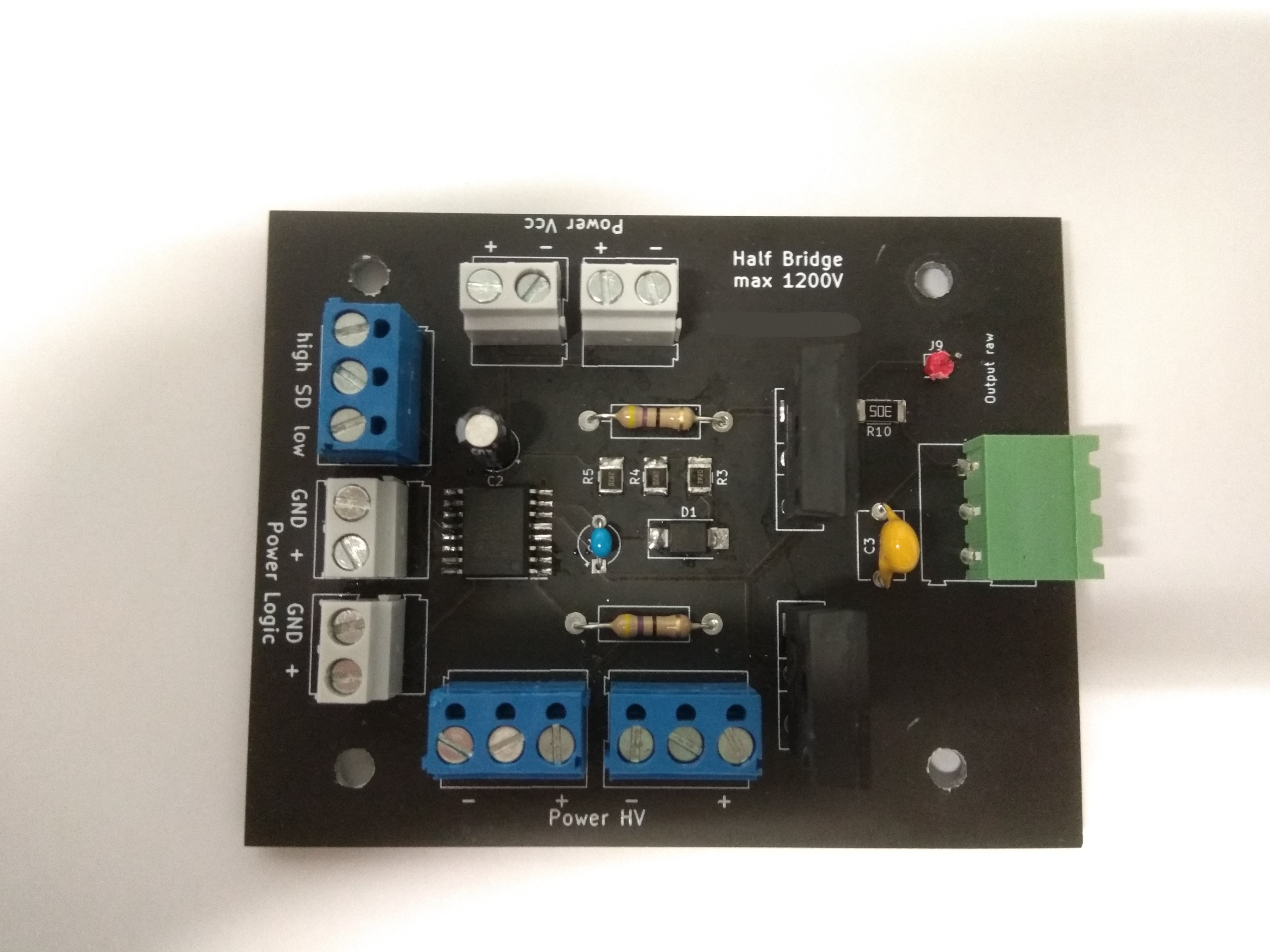 | 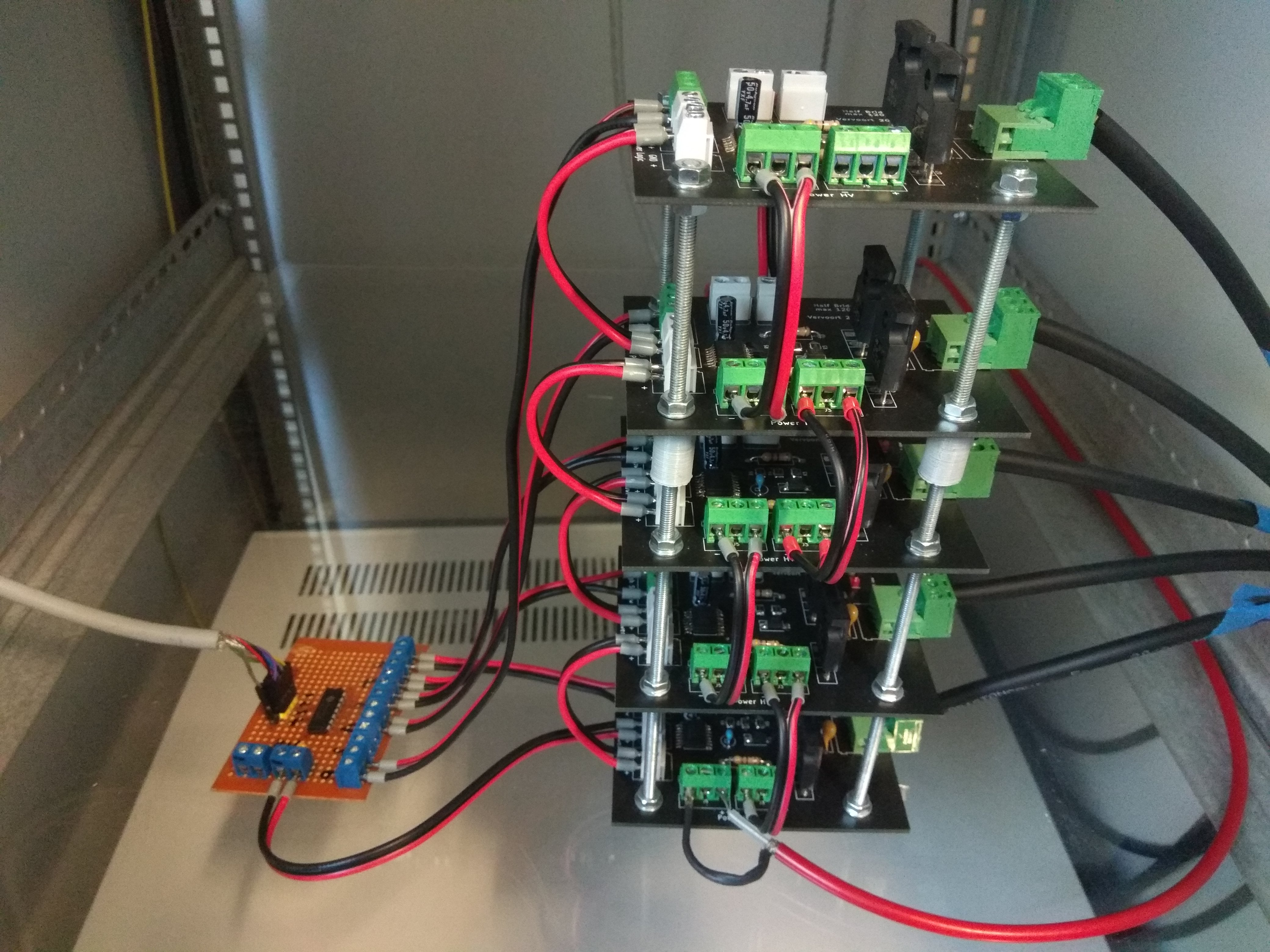 |
| single half bridge | stacked half bridges |
The quiescent current at 1000V and 20kHz is approximately 3 mA. The minimum voltage resolution is determined by the PWM resolution; for instance, with a 12-bit signal, the resolution is about 0.244V.
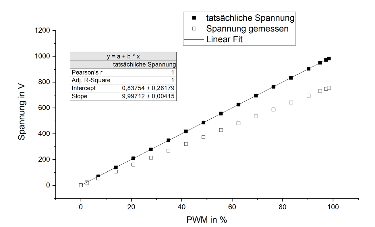
The voltage can be controlled linearly as desired:
| Qty | Value | Footprint | References |
|---|---|---|---|
| 4 | MountingHole | MountingHole:MountingHole_3.2mm_M3 | H1, H2, H3, H4 |
| 3 | 2.2 | Resistor_SMD:R_1210_3225Metric_Pad1.42x2.65mm_HandSolder | R3, R4, R5 |
| 2 | 47 | Resistor_THT:R_Axial_DIN0411_L9.9mm_D3.6mm_P15.24mm_Horizontal | R1, R2 |
| 2 | _ | Package_TO_SOT_THT:TO-247-3_Vertical | Q1, Q2 |
| 1 | 0.33u | Capacitor_THT:CP_Radial_Tantal_D4.5mm_P5.00mm | C1 |
| 1 | 1200V | Diode_SMD:D_SMB_Handsoldering | D1 |
| 1 | 150p | Capacitor_THT:C_Disc_D7.5mm_W5.0mm_P7.50mm | C3 |
| 1 | 240k | Resistor_SMD:R_2010_5025Metric_Pad1.52x2.65mm_HandSolder | R10 |
| 1 | 3u3 | Capacitor_THT:CP_Radial_D5.0mm_P2.00mm | C2 |
| 1 | FAN73912MX | 0_SamacSys_Parts:SOIC127P1032X265-16N | IC1 |
| 1 | Input_HV | TerminalBlock:TerminalBlock_Altech_AK300-3_P5.00mm | J3 |
| 1 | Input_Logic | TerminalBlock:TerminalBlock_Altech_AK300-2_P5.00mm | J6 |
| 1 | Input_Signal | TerminalBlock:TerminalBlock_Altech_AK300-3_P5.00mm | J1 |
| 1 | Input_VCC | TerminalBlock:TerminalBlock_Altech_AK300-2_P5.00mm | J2 |
| 1 | Output_Elektrode | TerminalBlock:TerminalBlock_Altech_AK300-3_P5.00mm | J8 |
| 1 | Output_HV | TerminalBlock:TerminalBlock_Altech_AK300-3_P5.00mm | J5 |
| 1 | Output_Logic | TerminalBlock:TerminalBlock_Altech_AK300-2_P5.00mm | J7 |
| 1 | Output_Raw | Connector_PinHeader_2.54mm:PinHeader_1x01_P2.54mm_Vertical | J9 |
| 1 | Output_VCC | TerminalBlock:TerminalBlock_Altech_AK300-2_P5.00mm | J4 |
It measures 91.4 × 71.1 mm and has 2 copper layers, 1.6 mm thick.
26 parts, built around the FAN73912MX. The full list of its parts is on this page, with links to each part's symbol and footprint where PCBKit's library has them.
From the Fersaar/adjustable_high_voltage_source repository on GitHub, at the commit this page was made from: the board is KiCad/hbruecke.kicad_pcb. PCBKit opens the board in the browser, with nothing to install.
Its repository publishes it under the GPL-3.0 licence: you may reuse it on that licence's terms (keep the author's notice, and for a copyleft licence share your changes alike).

hackclub/OnBoard
💡 Join 1,000 teenagers and make your first PCB with a $100 grant!


harbaum/galagino
A Galaga, Pac-Man and Donkey Kong arcade emulator for the ESP32

Luos-io/luos_engine
Open-source and real-time orchestrator for cyber-physical-systems, to easily design, test and deploy embedded applications and digital twins.

google/walt
A device for measuring latency of physical sensors and outputs on phones and computers
