2 layers130.3 × 107.9 mm
Knuckles wireless autorouted
fcoury/knuckles
An open-source, wireless column-staggered ergonomic keyboard.
121 parts6MIT

 fcoury/knuckles6
An open-source, wireless column-staggered ergonomic keyboard.
Knuckles is an open-source printed circuit board by fcoury, from the fcoury/knuckles repository on GitHub, published under the MIT licence. It is a 2-layer board of 130.3 × 107.9 mm with 152 parts on 134 nets, routed with 794 tracks and 132 vias.
Its parts include 87 diodes and 54 switches. It belongs with the keyboards and input boards of this library.

There are a lot of split keyboards out there, but most of the ones that piqued my interest don't have a number row, and I really like having one. I also wanted a slim ergo split that feels somewhat like a Magic Keyboard. Knuckles is my attempt at both.
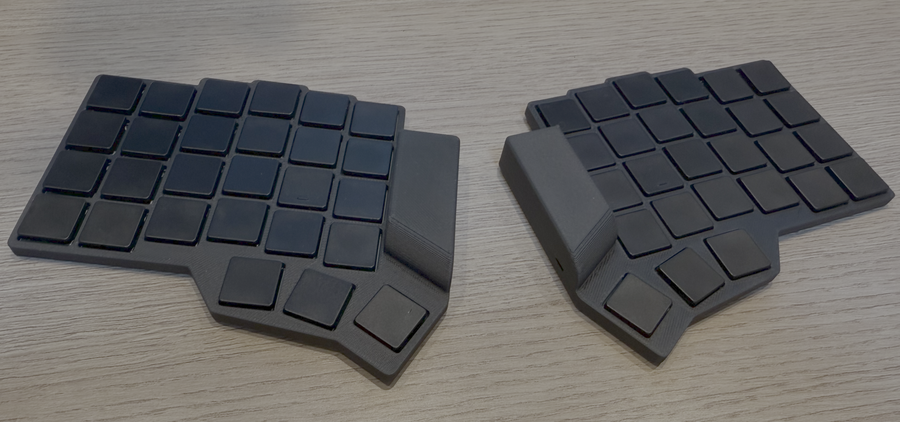
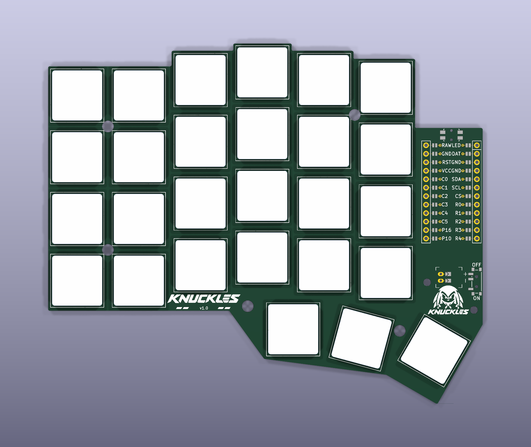
Each half has 27 keys: a column-staggered 6×4 grid that includes the number row, plus a three-key thumb fan. It uses Kailh PG1316S low-profile switches on reversible footprints, a nice!nano controller, a JST-PH battery connector, and a power switch. The controller area also fits the HolyKeebs TPS43 touchpad module.
The first wireless PCB was ordered from JLCPCB on 2026-10-18. The exact files
are archived in manufacturing/.
ergogen/config.yaml also still defines the original wired knuckles board
(TRRS, small display). It's no longer supported. knuckles_wireless is the
board to build.
A separate integrated nRF52840 revision adds on-board USB, charging and radio circuitry in dedicated left/right layouts. Its retained routed layouts and experimental firmware are engineering prototypes; module sourcing, manufacturing review and bench validation remain release gates. The normal build continues to use the nice!nano design.
You'll need Node.js 18+ (CI uses Node 20) and Git. Footprints live in a submodule, so clone recursively:
git clone --recursive https://github.com/fcoury/knuckles.git
cd knuckles
npm install
npm run build
npm run build runs Ergogen on ergogen/config.yaml and writes the PCBs,
plates, outlines, and bottom tray STL. npm run debug does the same with
Ergogen's debug output. npm run watch:build and npm run watch:debug rebuild
whenever the YAML or scripts change.
The default is 18.5 mm center to center. That's the compact layout and the one that was ordered. 19.5 mm is also available:
npm run build -- --spacing 19.5

# Keep both layouts side by side
npm run debug -- --spacing 18.5 --output build/18.5
npm run debug -- --spacing 19.5 --output build/19.5
Plates, holes, the silkscreen artwork, and the bottom tray all follow the
selected spacing. Run npm run build -- --help for all options. The
gotchas cover how spacing interacts with the other scripts.
The full pipeline also needs Docker. It runs KiCad 8, KiBot, and Freerouting in containers, pulling the images on first run.
./build.sh:
Other entry points:
./rebuild.sh re-exports and autoroutes the boards already in pcbs/
without running Ergogen.npm run route autoroutes only knuckles_wireless. It prunes dead-end
traces and tries up to three times. A route is accepted only if KiCad reports
no unconnected items, no dangling tracks, and no DRC errors../watch.sh (macOS, needs fswatch) regenerates the PCB when the config
changes and opens the result.Upload the KiBot ZIP from ergogen/output/gerbers/knuckles_wireless/ to
JLCPCB. Manufacturing output comes only from
pcbs/knuckles_wireless_autorouted.kicad_pcb. The KiBot configs
(kibot/default.kibot.yaml, kibot/boards.kibot.yaml) are tuned for JLCPCB.
The board uses a 0.25 mm copper-to-edge clearance for routed outlines.
Local builds and CI both route through scripts/autoroute.sh, with the same
KiCad image, Freerouting 2.1.0 JAR, rules, and optimizer settings. Freerouting
can still produce different trace geometry from run to run. That's why the
pipeline checks connectivity and DRC instead of comparing files byte for byte.
Each board that gets ordered goes in its own dated folder under
manufacturing/. Don't modify those files once they're archived.
.github/workflows/build.yaml runs the full pipeline for both spacings. Each
run uploads a knuckles-18.5mm and a knuckles-19.5mm artifact containing
cases, Gerbers, images, outlines, and PCBs. npm test runs real builds of both
layouts and checks spacing selection, the generated outputs, and rejection of
invalid values.
Everything starts in ergogen/config.yaml:
points.zones.*
(spacing, splay, stagger).meta.footprint and pick a preset (mx, choc_v1,
choc_v2, or the low-profile reversible footprints).mcu footprint section.cases/knuckles_bottom_tray.jscad and the
outlines/_bottom_case* outlines to change walls and cutouts.KiCad project settings in pcbs/ are generated, so edit
kicad/projects/knuckles_wireless.kicad_pro instead. The build copies it next
to the board.
The silkscreen badge and wordmark are documented in
artwork/knuckles/.
| Path | Contents |
|---|---|
ergogen/ | Ergogen config, footprints submodule, generated images and Gerbers |
pcbs/ | Generated KiCad boards and plates; autoroute/<board>/ holds DSN, SES, router log, and DRC report |
outlines/ | DXF/SVG outlines for the PCB, plates, and case |
cases/ | JSCAD bottom tray and generated STL; thin/ has slim case prototypes for older 18.5 mm boards |
kicad/projects/ | Canonical KiCad project settings |
kibot/ | KiBot configs and DSN/SES helper scripts |
freerouting/ | Autorouter rules and JAR |
hardware/integrated-controller/ | Opt-in integrated controller PCB and firmware prototypes, routed layouts and engineering checks |
manufacturing/ | Archived files for each ordered board |
artwork/ | Badge and wordmark sources and PCB renders |
images/ | Reference renders of the plates and controller overlay |
scripts/ | Build, autoroute, artwork, and case scripts |
--spacing overrides KNUCKLES_SPACING, which overrides the config
default. The YAML is never rewritten. pcbs/build-info.json records which
spacing was used../build.sh (KNUCKLES_SPACING=19.5 ./build.sh) always writes to the root
output folders. Use npm run build -- --output if you want them kept apart../rebuild.sh routes whatever board is already in pcbs/ and keeps its
spacing.ergogen/output/pcbs/ contains old snapshots that builds don't update.MIT. See LICENSE.
| Qty | Value | Footprint | References |
|---|---|---|---|
| 54 | — | ceoloide:diode_tht_sod123 | D1, D2, D10, D11, D12, D13, D14, D15, D16, D17, D18, D19, D20, D21, D22, D23 +38 |
| 54 | — | CPG1316S01D02 | S1, S2, S10, S11, S12, S13, S14, S15, S16, S17, S18, S19, S20, S21, S22, S23 +38 |
| 27 | — | ceoloide:led_SK6812mini-e (per-key, reversible) | LED1, LED2, LED10, LED11, LED12, LED13, LED14, LED15, LED16, LED17, LED18, LED19, LED20, LED21, LED22, LED23 +11 |
| 7 | — | ceoloide:mounting_hole_npth | MH1, MH2, MH3, MH4, MH5, MH6, MH7 |
| 6 | — | ceoloide:led_SK6812mini-e (underglow, reversible) | LED28, LED29, LED30, LED31, LED32, LED33 |
| 1 | — | ceoloide:trrs_pj320a (reversible, symmetric) | TRRS1 |
| 1 | — | ceoloide:mcu_nice_nano | MCU1 |
| 1 | — | ceoloide:reset_switch_tht_top | RST1 |
| 1 | — | ceoloide:display_ssd1306 | DISP1 |
It measures 130.3 × 107.9 mm and has 2 copper layers, 1.6 mm thick.
152 parts. The full list of its parts is on this page, with links to each part's symbol and footprint where PCBKit's library has them.
From the fcoury/knuckles repository on GitHub, at the commit this page was made from: the board is pcbs/knuckles.kicad_pcb and its schematic hardware/integrated-controller/output/core.kicad_sch. PCBKit opens the board in the browser, with nothing to install.
Its repository publishes it under the MIT licence: you may reuse it on that licence's terms (keep the author's notice, and for a copyleft licence share your changes alike).
fcoury/knuckles
An open-source, wireless column-staggered ergonomic keyboard.

fcoury/knuckles
An open-source, wireless column-staggered ergonomic keyboard.

fcoury/knuckles
An open-source, wireless column-staggered ergonomic keyboard.


TweetyDaBird/Lotus-58-Classic
A split ergo linear keyboard derived from the Lily58 family


ktec-hq/ErgoDone
ErgoDox using pro micro. Original work by Dox. Brainhole association present


