
2 layers45.7 × 31.8 mm
LEDx16 board
tardate/LittleArduinoProjects
a collection of "Little Electronic & Arduino Projects", most involving electronics or an Arduino in one way or another!
36 parts803MIT

 farazaleboyeh/led-matrix1
Graphics driver & hardware design for a custom-built display that shows streamed music artwork.
Led matrix is an open-source printed circuit board by farazaleboyeh, from the farazaleboyeh/led-matrix repository on GitHub. It is a 2-layer board of 154.7 × 125.7 mm with 160 parts on 141 nets, routed with 716 tracks and 15 vias.
It is built around the 74HC595. Its parts include 100 diodes, 10 transistors, 5 ICs and 3 connectors. It belongs with the lEDs and displays boards and the ESP32 boards of this library.
The purpose of this project has been to extend my skills as a hardware engineer, specifically in regards to the development of embedded systems. Thus, I challenged myself to build a complete system from scratch that encompasses the entire development lifecycle. From schematic design and PCB layout in KiCad, to writing the C++ firmware for Wi-Fi networking, memory management, & custom LED multiplexing.
Repository includes the firmwmare used to show the artwork of a currently streaming song from Spotify onto a custom-built 10x10 display, as well as all primary KiCad project files used to design the system itself. Some examples images of the display in its most recent state are available below.

Example 1, raw LEDs exposed. |

Example 2, raw LEDs exposed. |

Example 3, makeshift diffuser overlayed. |

Example 4, makeshift diffuser overlayed. |
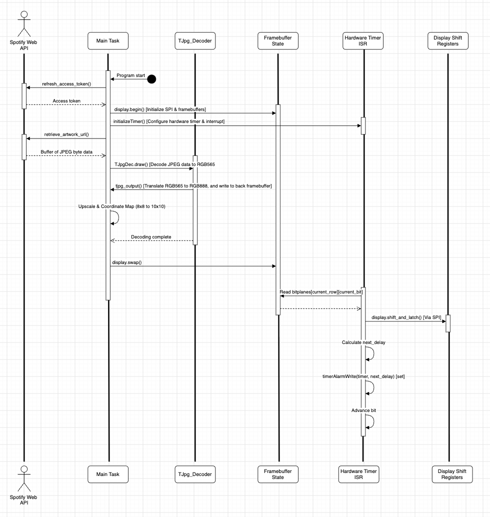
The system works by first calling Spotify's APIs to fetch all data regarding the user's playing music. From the given information, a link to the album art is then used to store all JPEG data (as a stream of bytes) to an internal buffer. The TJpg Decoder library is used to decode the buffer as RGB565 data (locally), which perpetually reaches out to a separate callback function, which converts again to RGB888 and also writes to the display's back framebuffer. When the front and back framebuffers are swapped, a continuously firing interrupt displays the artwork by streaming the bitplanes (sequentially by time slice and physical row), to the display's shift registers.
The display is driven by an ESP32 microcontroller, which is responsible for streaming color data to the chained shift registers, among other tasks. Transistors are present along all rows which act as high-side power switches between the main power rail and the shared anodes, so that the (output-limited) shift registers are not solely responsible for driving entire rows themselves. 1kΩ current-limiting resistors are present along rows to protect the shift registers and LEDs from overheating & overcurrent, with per-color resistors along each column to finely tune color output (100Ω for red columns, 150Ω, green, & 220Ω blue). Images of the schematic, PCB design, & soldered board are all shown below for reference.
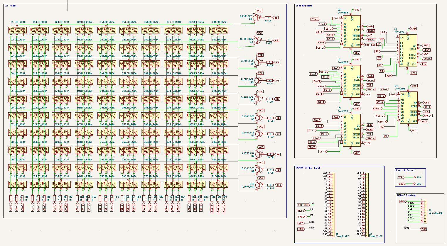
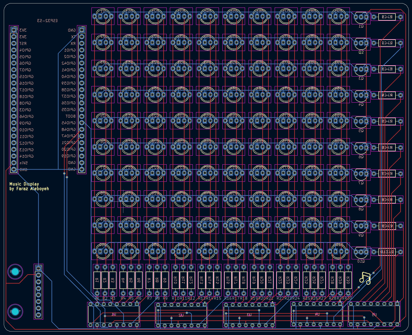
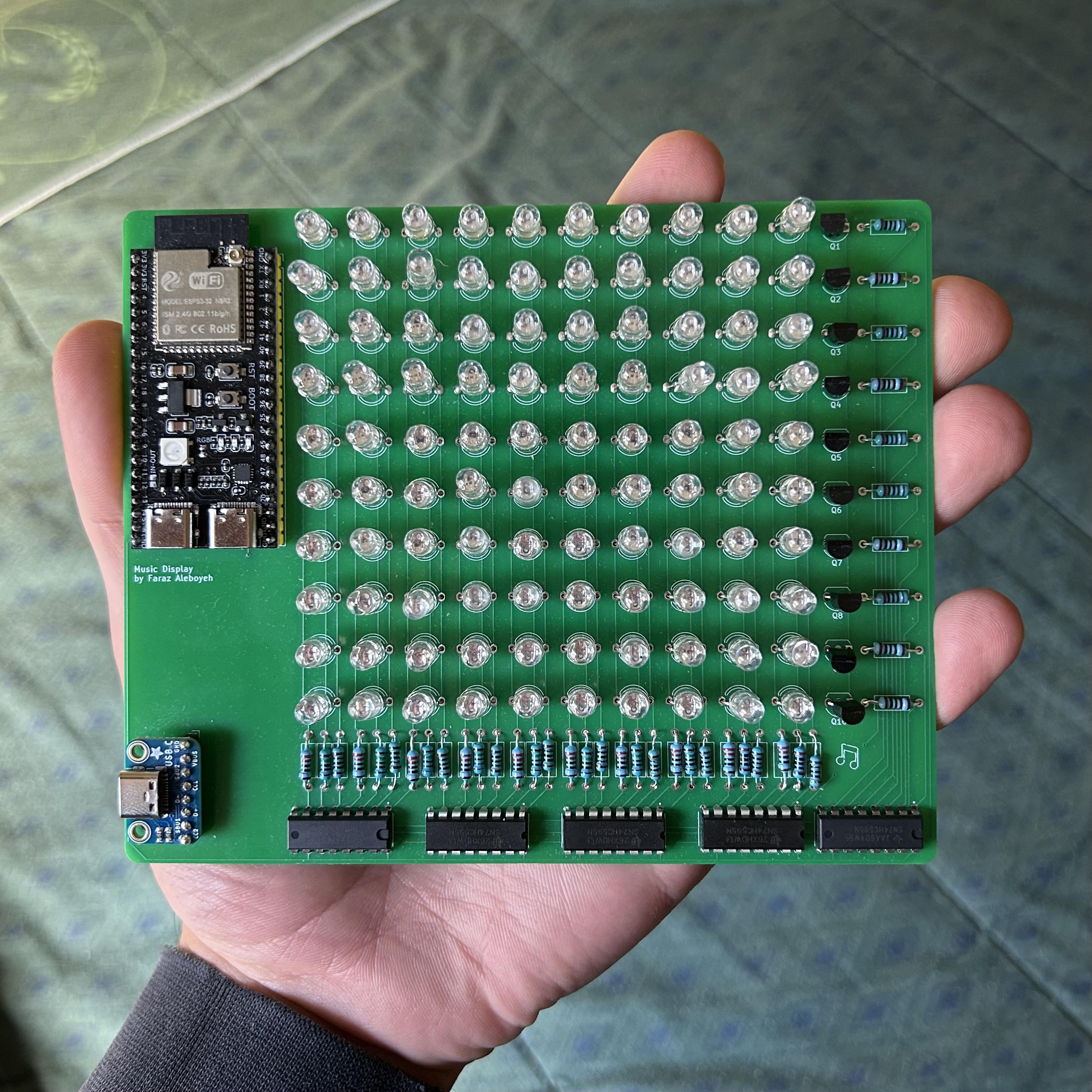
The basis of the project lies in interfacing with Spotify's APIs to receieve user data regarding their currently playing music. Every time the program begins running, and after a successful Wi-Fi connection is established, one of the first tasks to run is the retrieval of a new Access Token from Spotify's servers. As per the Spotify's requirements, Access Tokens are inherently ephemeral, expiring automatically every 3600 seconds (1 hour) regardless of scope. Thus, a function runs every 55 minutes to renew the Activation Token automatically, ensuring the display can be used for extended periods of time.
There is not currently, however, any avenue for renewing the Refresh Tokens automatically at the time of writing. Given they expire every 4 months, an implementation for such was not listed as high-enough priority but is in the works.
Instead of standard PWM, which would demand an unsustainable 2,550 SPI updates per frame (10 rows x 255 steps) and cause severe CPU starvation, the driver implements Binary Code Modulation via the microcontroller's hardware timer. By shifting only 8 exponentially weighted bitplanes per row (5µs, 10µs, 20µs, etc.), BCM slashes bus traffic by 97% to just 80 updates per frame, reconstructing full 8-bit color depth through visual persistence while leaving the CPU free for WiFi and JPEG decoding.
To prevent screen tearing during WiFi fetches or JPEG decoding: Operations draw to a back framebuffer (draw_buffer), display.swap() unpacks the back buffer into physical bitplanes (bitplanes[10][8][5]), & the ISR (on_timer) exclusively reads from the active bitplanes.
A list of the main tasks in progress for this project:
A non-exhaustive list of ideas for future iterations of this project:
| Qty | Value | Footprint | References |
|---|---|---|---|
| 100 | LED_RGBA | LED_THT:LED_D5.0mm-4_RGB_Wide_Pins | D1, D2, D10, D11, D12, D13, D14, D15, D16, D17, D18, D19, D20, D21, D22, D100 +84 |
| 40 | R | Resistor_THT:R_Axial_DIN0207_L6.3mm_D2.5mm_P10.16mm_Horizontal | R-C1, R-C2, R-C3, R-C4, R-C5, R-C6, R-C7, R-C8, R-C9, R-C10, R1, R10, R11, R12, R13, R14 +24 |
| 9 | Q_PNP_BCE | Package_TO_SOT_THT:TO-92_Inline_Wide | Q1, Q2, Q3, Q4, Q5, Q6, Q7, Q8, Q9 |
| 5 | 74HC595 | SN74HC595N hi:DIP794W45P254L1969H508Q16 | U1, U2, U3, U4, U5 |
| 2 | Conn_01x22 | Connector_PinSocket_2.54mm:PinSocket_1x22_P2.54mm_Vertical | J1, J2 |
| 1 | Conn_01x08 | Connector_PinSocket_2.54mm:PinSocket_1x08_P2.54mm_Vertical | J3 |
| 1 | Q_PNP_EBC | Package_TO_SOT_THT:TO-92_Inline_Wide | Q10 |
The 158 most common of 160 parts.
tardate/LittleArduinoProjects
a collection of "Little Electronic & Arduino Projects", most involving electronics or an Arduino in one way or another!

ChrisChrisLoLo/beyblock20
The magnetic, modular, 20-key macropad that can join together to form an ortholinear board

slu4coder/Minimal-64x4-Home-Computer
My DIY TTL home computer with VGA and PS/2 and 4x the processing power of a Commodore C64 or Apple II.

electroniceel/protoboard
Advanced protoboard layout with 1.27mm pitch for smd parts

TobleMiner/DC-UPS
A small DC UPS, designed to keep small appliances like consumer network equipment running during power outages


It measures 154.7 × 125.7 mm and has 2 copper layers, 1.6 mm thick.
160 parts, built around the 74HC595. The full list of its parts is on this page, with links to each part's symbol and footprint where PCBKit's library has them.
From the farazaleboyeh/led-matrix repository on GitHub, at the commit this page was made from: the board is hardware/led-matrix.kicad_pcb and its schematic hardware/led-matrix.kicad_sch. PCBKit opens the board in the browser, with nothing to install.
Its repository states no licence, so its author keeps all rights: ask farazaleboyeh before reusing the design.