2 layers144.8 × 73.7 mm

 Faizul6/sensor-fusion-module
A miniaturized multi-sensor module that combines distance, motion, vibration, and light sensing into a single environment-awareness output — designed and documented like a real inspection-robot sensor module…
Sensor fusion module is an open-source printed circuit board by Faizul6, from the Faizul6/sensor-fusion-module repository on GitHub. It is a 2-layer board with 6 parts on 42 nets, routed with 54 tracks and 0 vias.
It is built around the ESP32-WROOM-32, ADXL343BCC and HC-SR04. Its parts include 2 resistors, 2 ICs and 2 connectors. It belongs with the sensors and measurement boards and the ESP32 boards of this library.


A miniaturized multi-sensor module that combines distance, motion, vibration, and light sensing into a single environment-awareness output — designed and documented like a real inspection-robot sensor module: schematic-first, bus-based, with a routed PCB layout.
This project focuses on the hardware design side of sensor integration for mobile/inspection robotics: schematic capture, PCB layout with a genuine I2C bus device, and design-rule validation using KiCad.
The module integrates four sensing modalities on a single board built around an ESP32-WROOM-32:
The ADXL343 was chosen specifically as a genuine I2C bus device, so the design demonstrates real bus-based sensor integration (SDA/SCL) rather than only GPIO-polled sensors.
| Component | Function | Interface |
|---|---|---|
| ESP32-WROOM-32 | MCU / host controller | — |
| HC-SR04 | Ultrasonic distance | GPIO (TRIG/ECHO) |
| HC-SR501 (PIR) | Motion detection | GPIO (digital out) |
| ADXL343 | Accelerometer | I2C |
| LDR + 10kΩ resistor | Light level | Analog (voltage divider) |
All components are from existing hardware stock — no new purchases were made for this project.
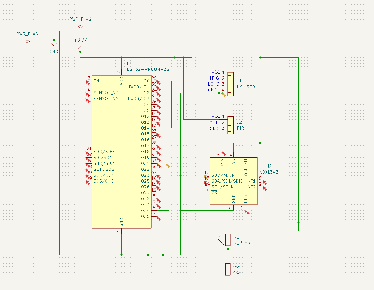
Power distribution (+3.3V/GND via PWR_FLAG), HC-SR04 (TRIG=IO13, ECHO=IO12), PIR (OUT=IO27), ADXL343 in I2C mode (SDA=IO21, SCL=IO22, CS tied to +3.3V, SDO/ADDR tied to GND), and the LDR divider feeding IO34.
Electrical Rules Check (ERC) passed cleanly; the only remaining warnings are expected "unused pin" notices on unconnected ESP32 GPIOs, which is normal and intentional for this design.
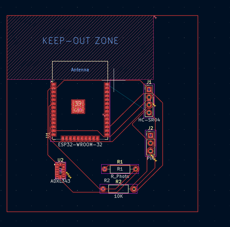
Key layout notes:
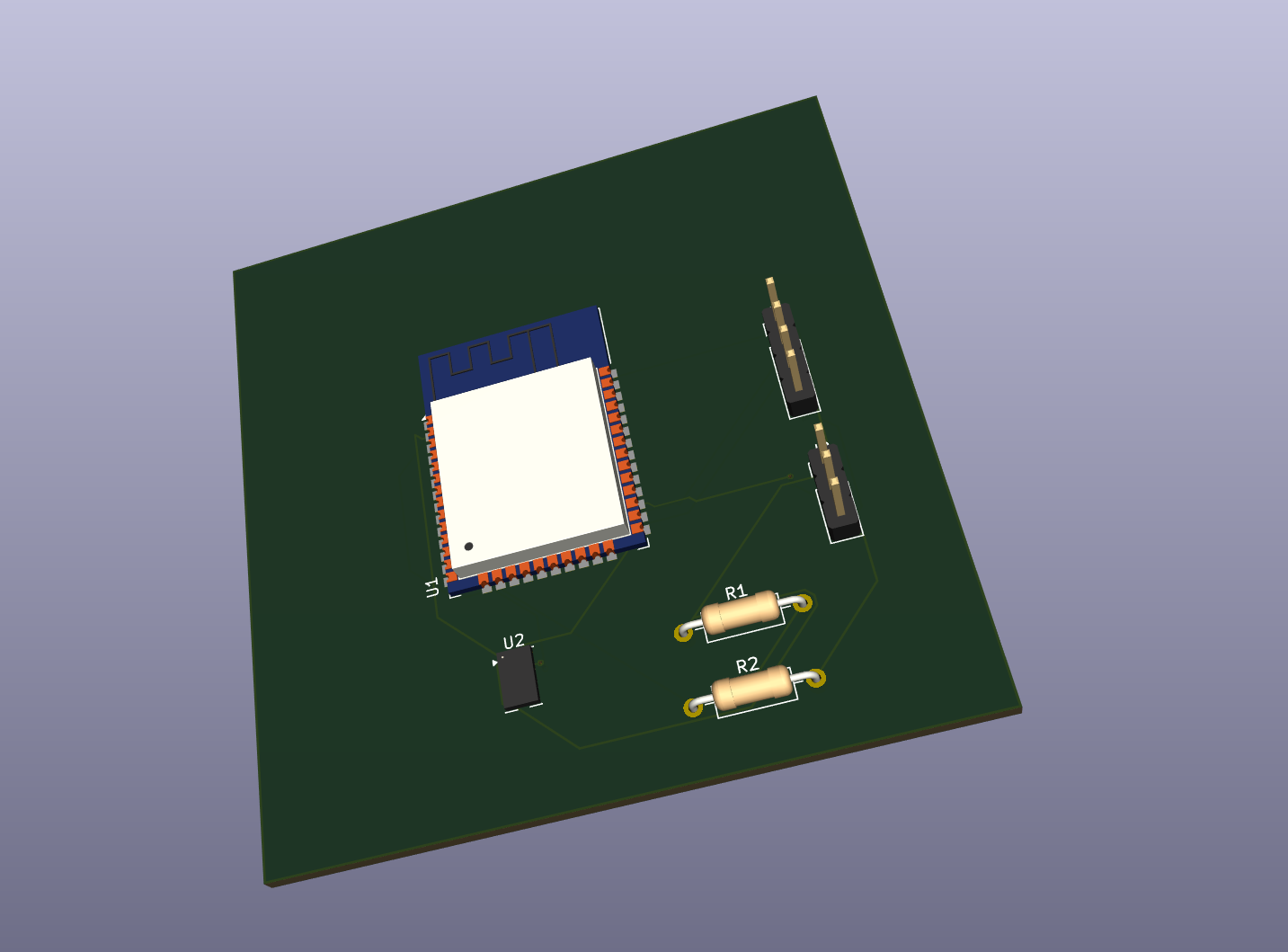
This project is scoped as a documentation/design exercise, not a fabrication-ready board. As such, three DRC items were reviewed:
images/ — README figuressensor-fusion-module.kicad_sch — Schematicsensor-fusion-module.kicad_pcb — PCB layoutsensor-fusion-module.kicad_pro — KiCad project filesensor-fusion-module.pdf — Schematic export (PDF)sensor-fusion-module-F_Cu.pdf — PCB layer export (PDF)| Qty | Value | Footprint | References |
|---|---|---|---|
| 1 | 10K | Resistor_THT:R_Axial_DIN0207_L6.3mm_D2.5mm_P10.16mm_Horizontal | R2 |
| 1 | ADXL343 | Package_LGA:LGA-14_3x5mm_P0.8mm_LayoutBorder1x6y | U2 |
| 1 | ESP32-WROOM-32 | RF_Module:ESP32-WROOM-32 | U1 |
| 1 | HC-SR04 | Connector_PinHeader_2.54mm:PinHeader_1x04_P2.54mm_Vertical | J1 |
| 1 | PIR | Connector_PinHeader_2.54mm:PinHeader_1x03_P2.54mm_Vertical | J2 |
| 1 | R_Photo | Resistor_THT:R_Axial_DIN0207_L6.3mm_D2.5mm_P10.16mm_Horizontal | R1 |
6 parts, built around the ESP32-WROOM-32, ADXL343BCC and HC-SR04. The full list of its parts is on this page, with links to each part's symbol and footprint where PCBKit's library has them.
From the Faizul6/sensor-fusion-module repository on GitHub, at the commit this page was made from: the board is sensor-fusion-module.kicad_pcb and its schematic sensor-fusion-module.kicad_sch. PCBKit opens the board in the browser, with nothing to install.
Its repository states no licence, so its author keeps all rights: ask Faizul6 before reusing the design.

Sahil073/SIH_GLAH10_BrajCoders
This directory contains the schematic design, printed circuit board (PCB) layout, 3D renderings, and manufacturing guidelines for the Sanjeevni wearable hardware prototype, designed using KiCad.

c-lydia/ESP-ROS2
A tiny robot with IMU (MPU5060) and an ultrasonic sensor (HC-SR04), running on micro-ROS, communicating over UDP.

CITROMOSEPER/4-zone-irrigation-system-2026-TDK-Project
Négyzónás, ESP32-alapú adatvezérelt öntözőrendszer: érzékelők és időjárás-előrejelzés alapján dönt a vízadagról, három üzemmóddal, telefonos webes felülettel és biztonsági réteggel. TDK-projekt, Óbudai Egyetem, 2026.


yagiz-bas/ESP32-Smart-Target-Detection-System
A compact ESP32-based target detection and alarm system using an HC-SR04 ultrasonic sensor, an SG90 servo, an SSD1306 OLED display, a buzzer, and a red LED.


acha666/RP2040_ToolheadPCB_SB
A Toolhead PCB for VORON StealthBurner based on RP2040