
2 layers110.5 × 102.9 mm

 failsmakes/RC_Receiver_PCB_ESP32-WROOM
Bu proje, RC-Receiver-ESP yazılımı için tasarlanmış ESP32-WROOM tabanlı RC alıcı devresinin PCB çizimini içerir. Tasarım KiCad 10.0.1 ile hazırlanmıştır.
RC Receiver PCB ESP32-WROOM is an open-source printed circuit board by failsmakes, from the failsmakes/RC_Receiver_PCB_ESP32-WROOM repository on GitHub, published under the AGPL-3.0 licence. It is a 2-layer board of 30 × 62.5 mm with 16 parts on 36 nets, routed with 84 tracks and 1 via.
It is built around the RZ7886. Its parts include 4 ICs, 3 connectors, 2 resistors and 1 capacitor. It belongs with the ESP32 boards of this library.
Bu proje, RC-Receiver-ESP yazılımı için tasarlanmış ESP32-WROOM tabanlı RC alıcı devresinin PCB çizimini içerir. Tasarım KiCad 10.0.1 ile hazırlanmıştır.
Bu kart, RC sinyallerini ESP32 üzerinden işleyebilmek için optimize edilmiştir. Üzerinde güç regülasyonu, servo ve motor çıkışları, MPU6050 sensör bağlantısı ve MP1584 voltaj modülü için yerleşim alanları bulunur.
RC_Receiver_PCB_ESP32-WROOM.kicad_pcb → PCB çizimiRC_Receiver_PCB_ESP32-WROOM.sch → Şematik dosyasıMakerZ RC Receiver ESP32 WROOM Schematic.pdf → Şema PDF çıktısıgerber/ → Üretim dosyalarıREADME.md → Bu açıklama dosyası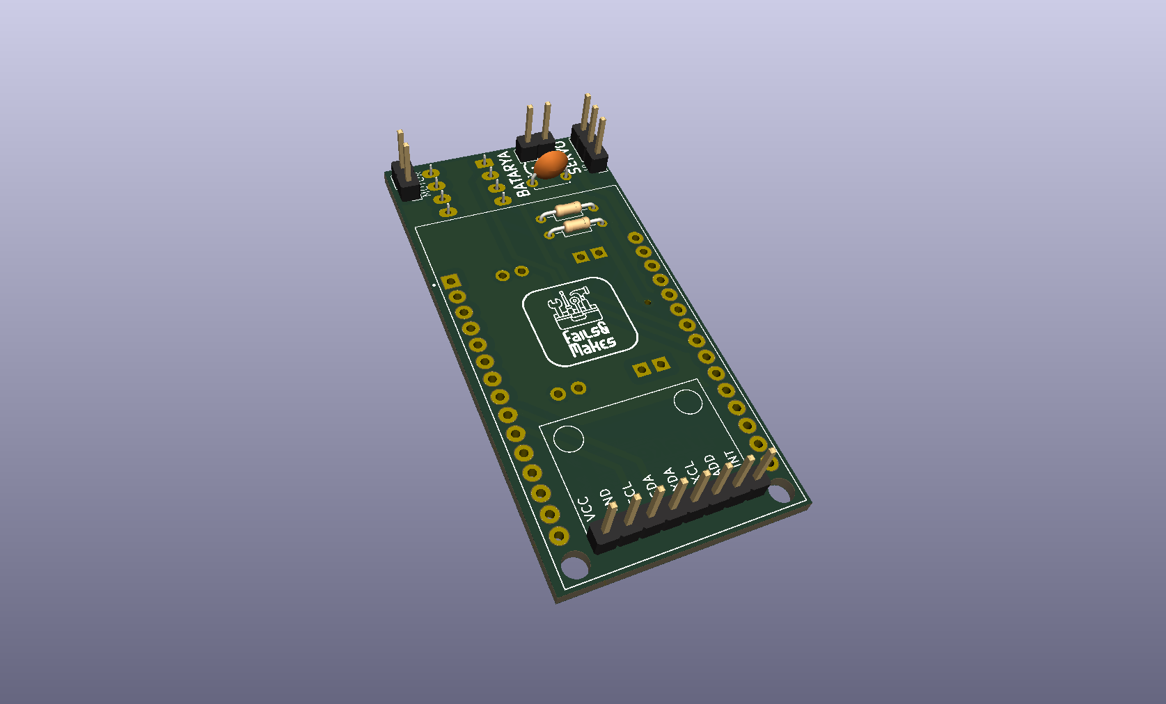
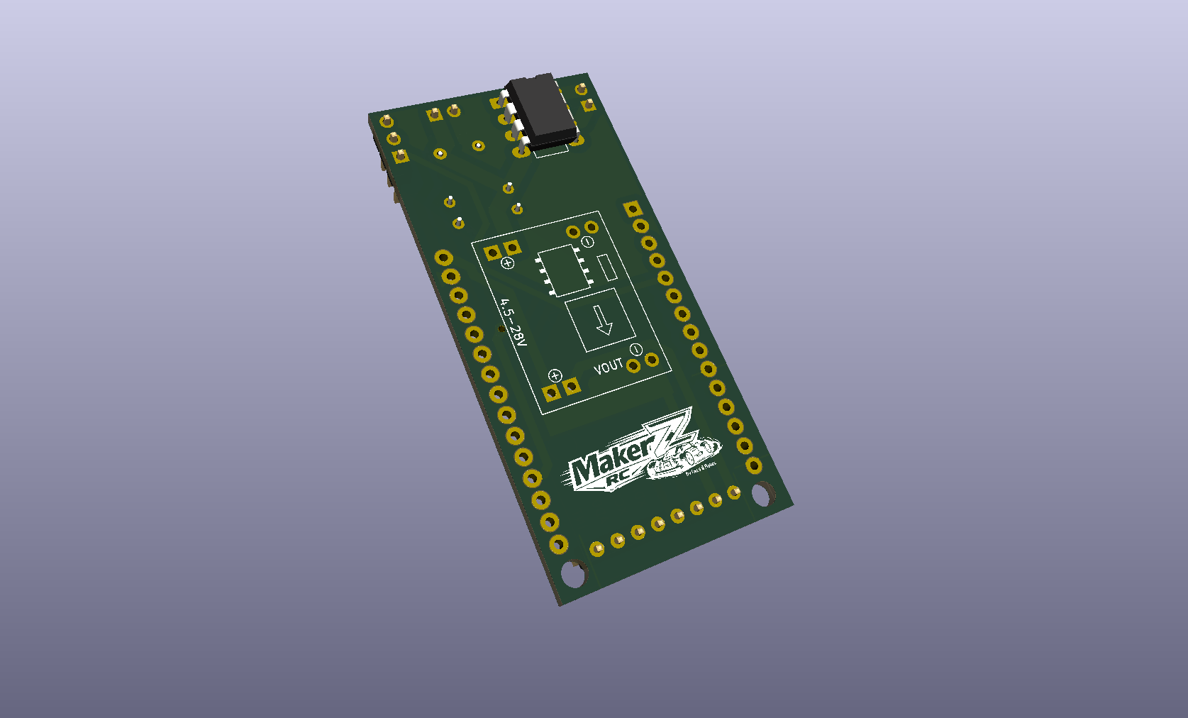
gerber/ klasöründeki dosyaları kullanarak PCB üretimi yaptırabilirsiniz.Bu PCB tasarımı, RC-Receiver-ESP yazılım projesi ile birlikte kullanılmak üzere hazırlanmıştır.
Bu proje açık kaynaklıdır. Detaylar için lisans dosyasına göz atın.
| Qty | Value | Footprint | References |
|---|---|---|---|
| 1 | 100nF | Capacitor_THT:C_Disc_D5.0mm_W2.5mm_P5.00mm | C1 |
| 1 | 10K | Resistor_THT:R_Axial_DIN0204_L3.6mm_D1.6mm_P7.62mm_Horizontal | R2 |
| 1 | 47K | Resistor_THT:R_Axial_DIN0204_L3.6mm_D1.6mm_P7.62mm_Horizontal | R1 |
| 1 | Conn_01x02 | Connector_PinHeader_2.54mm:PinHeader_1x02_P2.54mm_Vertical | J4 |
| 1 | DEVKIT_V1_ESP32-WROOM-32 | DOIT-DEVKIT_V1_ESP32-WROOM-32:MODULE_DEVKIT_V1_ESP32-WROOM-32 | U6 |
| 1 | LOGO | MEHMET:Fails&Makes-Logo-12x12mm | G*** |
| 1 | MP1584_Module | MEHMET:SRT_MPT1584EN_Module | U2 |
| 1 | Motor | Connector_PinHeader_2.54mm:PinHeader_1x02_P2.54mm_Vertical | J2 |
| 1 | RZ7886 | Package_DIP:DIP-8_W7.62mm_LongPads | U1 |
| 1 | Servo | Connector_PinHeader_2.54mm:PinHeader_1x03_P2.54mm_Vertical | J3 |
| 1 | module_mpu6050 | usini_sensors:module_mpu6050 | U4 |
The 11 most common of 16 parts.


google/mozc-devices
Circuit diagrams and firmware source code for Gboard DIY keyboards

conorpp/u2f-zero
U2F USB token optimized for physical security, affordability, and style

rusefi/rusefi
rusefi - GPL internal combustion engine control unit

VoronDesign/Voron-Hardware
Cool Hardware designed by the Voron Design group

hoglet67/RGBtoHDMI
Bare-metal Raspberry Pi project that provides pixel-perfect sampling of Retro Computer RGB/YUV video and conversion to HDMI

hackclub/OnBoard
💡 Join 1,000 teenagers and make your first PCB with a $100 grant!
It measures 30 × 62.5 mm and has 2 copper layers, 1.8 mm thick.
16 parts, built around the RZ7886. The full list of its parts is on this page, with links to each part's symbol and footprint where PCBKit's library has them.
From the failsmakes/RC_Receiver_PCB_ESP32-WROOM repository on GitHub, at the commit this page was made from: the board is RC_Receiver_PCB_ESP32-WROOM.kicad_pcb and its schematic RC_Receiver_PCB_ESP32-WROOM.kicad_sch. PCBKit opens the board in the browser, with nothing to install.
Its repository publishes it under the AGPL-3.0 licence: you may reuse it on that licence's terms (keep the author's notice, and for a copyleft licence share your changes alike).