2 layers52.2 × 52.2 mm
Base promicro
google/mozc-devices
Circuit diagrams and firmware source code for Gboard DIY keyboards
30 parts3kApache-2.0
 fablabbcn/cablebottt
Software and Hardware for Fab26 Boston's cable bot workshop
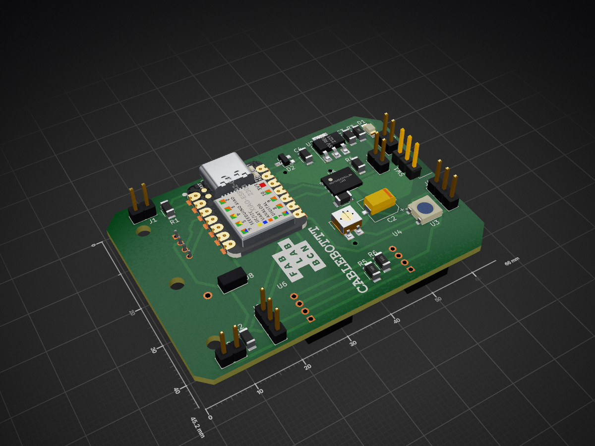
Fab26 cablebot is an open-source printed circuit board by fablabbcn, from the fablabbcn/cablebottt repository on GitHub. It is a 2-layer board of 66 × 45.2 mm with 30 parts on 24 nets, routed with 177 tracks and 3 vias.
Its parts include 7 ICs, 7 connectors, 6 resistors, 4 capacitors and 2 diodes. It belongs with the robots and motor control boards and the ESP32 and RISC-V boards of this library.
A hands-on STEAM workshop by FLU @ Fab Lab Barcelona.
Design, fabricate and program a cable-driven robot (cablebot). Participants build a small robot that travels along a cable using a rotating motor, and bring it to life by wiring up inputs (light, distance) and outputs (motor, LED, buzzer, servo). The activity combines mechanics + digital fabrication + computational thinking in an accessible, creative format.
Based on a yellow gearmotor driven from a Seeed Studio XIAO ESP32-C3, on a custom PCB.
The cablebot comes in two behaviors, using the same hardware:
| Sketch A — autonomous | Sketch B — teleoperated | |
|---|---|---|
| Idea | The robot decides for itself | You drive it from your phone |
| How | Follows light using 2 LDR sensors | Serves a webapp over its own WiFi |
| Inputs | 2 light sensors (LDR) | Distance sensor (optional) |
| Outputs | Motor | Motor, color LED, buzzer, servo |
| Libraries | None | Adafruit NeoPixel + VL53L1X |
| Best for | Seeing a closed feedback loop | Programming your own behaviors |
Both are fully documented — see Programming below.
cablebottt/
├── README.md                        ← you are here (project index)
│
├── fabrication/                     ← everything you cut / print / mill
│   ├── ⟨laser_pieces.svg⟩           ← laser-cut structure (the 3 assembly pieces)
│   ├── ⟨mount_3d.stl⟩               ← 3D-printed parts (if any)
│   ├── pcb/                         ← custom PCB (KiCad project + Gerbers)
│   │   ├── fab26_cablebot.kicad_pro
│   │   ├── fab26_cablebot.kicad_sch
│   │   ├── fab26_cablebot.kicad_pcb
│   │   ├── gerber/                  ← ready-to-mill / ready-to-order
│   │   └── svg/fab26_cablebot-preview.svg
│   └── silkscreen/back_silkscreen.svg
│
├── code/
│   ├── cablebottt_laser/cablebottt.ino        ← Sketch A (autonomous)
│   └── cablebottt_web/cablebottt_web.ino      ← Sketch B (teleoperated)
│
├── docs/
│   ├── cablebottt_sketch_A_tutorial.md        ← how to program Sketch A
│   └── cablebottt_sketch_B_tutorial.md        ← how to program Sketch B
│
└── images/                          ← photos & reference
    ├── ⟨assembled_bot.jpg⟩
    ├── ⟨soldering_xiao.jpg⟩
    └── ⟨pcb_render.png⟩
⟨…⟩ = placeholder. Replace with your real filenames. If the layout above doesn't match how you organized the folder, adjust the paths — the section links below still work as long as the two
docs/…tutorials keep their names.
Do it in three stages. Each stage has its own detailed doc; this index just tells you the order.
| Part | File | Process |
|---|---|---|
| Structure | fabrication/⟨laser_pieces.svg⟩ | Laser-cut, then assemble the 3 pieces |
| Custom PCB | fabrication/pcb/gerber/ | Mill or order from the Gerbers |
| Board | Seeed Studio XIAO ESP32-C3 | Solder the header pins onto the PCB |
Populate the PCB, solder the XIAO, attach the motor and the laser pointer, and assemble the laser-cut structure. Photos in images/.
The XIAO pinout, shared across both sketches:
| Function | Pin | Used by |
|---|---|---|
| Motor driver 1 / 2 | D9 / D10 | both |
| LDR left / right | A1 / A0 | Sketch A |
| NeoPixel (LED) | D7 | Sketch B |
| Buzzer | D6 | Sketch B |
| Servo | D8 | Sketch B |
| Distance sensor SDA / SCL | D4 / D5 | Sketch B |
Pick the behavior and follow its step-by-step tutorial:
docs/cablebottt_sketch_A_tutorial.md
No libraries needed. Upload and go.docs/cablebottt_sketch_B_tutorial.md
Install 2 libraries, then connect your phone to the CABLEBOTTT WiFi network.Both tutorials cover the one-time Arduino IDE + ESP32-C3 setup, so you only need to read it once.
CABLEBOTTT (password cablebottt), open http://192.168.4.1, and drive it.Originally created for a FAB26 Boston workshop. Repo: github.com/fablabbcn/cablebottt.
| Qty | Value | Footprint | References |
|---|---|---|---|
| 2 | 0.1uf | PCM_fab:C_1206 | C3, C4 |
| 2 | 5k | PCM_fab:R_1206 | R5, R6 |
| 2 | Grove I2C | OPL_Connector:GROVE-HW4-2.0-90D | U4, U6 |
| 2 | LDR | PCM_fab:PinHeader_01x02_P2.54mm_Vertical_THT_D1mm | J1, J2 |
| 2 | LOGO | LOGO | G***, G*** |
| 2 | TBD | PCM_fab:R_1206 | R1, R2 |
| 1 | 0.1uF | PCM_fab:C_1206 | C1 |
| 1 | 1k | PCM_fab:R_1206 | R3 |
| 1 | 5V REG | PCM_fab:SOT-223-3_TabPin2 | U2 |
| 1 | 9V BATTERY | PCM_fab:PinHeader_01x02_P2.54mm_Vertical_THT_D1mm | J3 |
| 1 | BUZZER | PCM_fab:PinHeader_01x02_P2.54mm_Vertical_THT_D1mm | J8 |
| 1 | CP_Elec_100uF_Panasonic_EEE-FN1E101UL | PCM_fab:CP_Elec_100uF_Panasonic_EEE-FN1E101UL | C2 |
| 1 | Diode_Schottky_ZLLS1000TA | PCM_fab:SOT-23 | D2 |
| 1 | Grove Extra | OPL_Connector:GROVE-HW4-2.0-90D | U7 |
| 1 | MOTOR | PCM_fab:PinHeader_01x02_P2.54mm_Vertical_THT_D1mm | J5 |
| 1 | MotorDriver_BrushedDC_Toshiba_TB67H451FNG | PCM_fab:HSOP-8 | U5 |
| 1 | Neopixel | PCM_fab:LED_ADDR_Worldsemi_WS2812B | U3 |
| 1 | Neopixel continued | PCM_fab:PinHeader_01x03_P2.54mm_Vertical_THT_D1mm | J4 |
| 1 | ON/OFF | PCM_fab:Switch_Slide_RightAngle_CnK_AYZ0102AGRLC_7.2x3mm | SW1 |
| 1 | PWR | PCM_fab:LED_1206 | D1 |
| 1 | R_POT_10K_Trimmer | PCM_fab:Potentiometer_TT_Model-23_4.5x5.0x3.0mm | RV1 |
| 1 | Servo | PCM_fab:PinHeader_01x03_P2.54mm_Vertical_THT_D1mm | J6 |
| 1 | TBD - current sense (0.2, 0.5) | PCM_fab:R_1206 | R4 |
| 1 | XIAO-ESP32-C3-DIP | Seeed_Studio_XIAO_Series:XIAO-ESP32-C3-DIP | U1 |
It measures 66 × 45.2 mm and has 2 copper layers, 1.6 mm thick.
30 parts. The full list of its parts is on this page, with links to each part's symbol and footprint where PCBKit's library has them.
From the fablabbcn/cablebottt repository on GitHub, at the commit this page was made from: the board is pcb/fab26_cablebot.kicad_pcb and its schematic pcb/fab26_cablebot.kicad_sch. PCBKit opens the board in the browser, with nothing to install.
Its repository states no licence, so its author keeps all rights: ask fablabbcn before reusing the design.
google/mozc-devices
Circuit diagrams and firmware source code for Gboard DIY keyboards


VoronDesign/Voron-Hardware
Cool Hardware designed by the Voron Design group

hoglet67/RGBtoHDMI
Bare-metal Raspberry Pi project that provides pixel-perfect sampling of Retro Computer RGB/YUV video and conversion to HDMI

tenderlove/initial-v
It's a BMW shifter converted to a Bluetooth Keyboard that you use with Vim

hackclub/OnBoard
💡 Join 1,000 teenagers and make your first PCB with a $100 grant!

