
2 layers30.5 × 63.5 mm
Board nfz330 nfz400
fabio-d/minitel-native
Software and hardware tools to run native programs on the Minitel
24 parts10CERN-OHL-W-2.0

 fabio-d/minitel-native10
Software and hardware tools to run native programs on the Minitel
Board 722039m is an open-source printed circuit board by fabio-d, from the fabio-d/minitel-native repository on GitHub, published under the CERN-OHL-W-2.0 licence. It is a 2-layer board of 93.2 × 67 mm with 24 parts on 85 nets, routed with 506 tracks and 50 vias.
It is built around the 23LCV512-E/P, SN74CB3T16211DL and 1N5819WS. Its parts include 6 capacitors, 6 resistors, 3 ICs, 2 connectors and 1 diode.


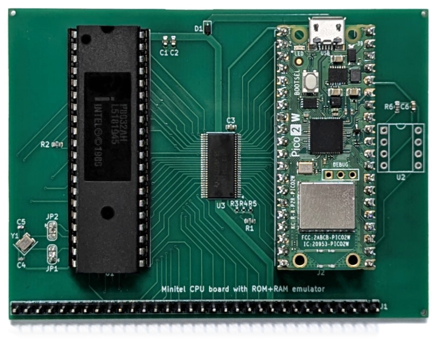
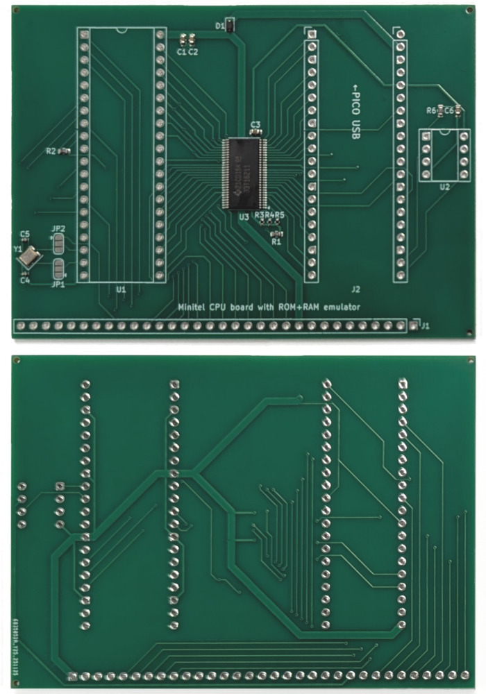
This board supports the following Minitel models:
Note: the battery1-powered RAM chip is optional. If omitted (or if no batteries are installed), the Minitel will lose its address book and messages at every boot.
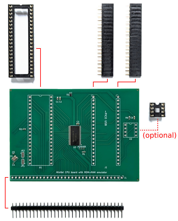
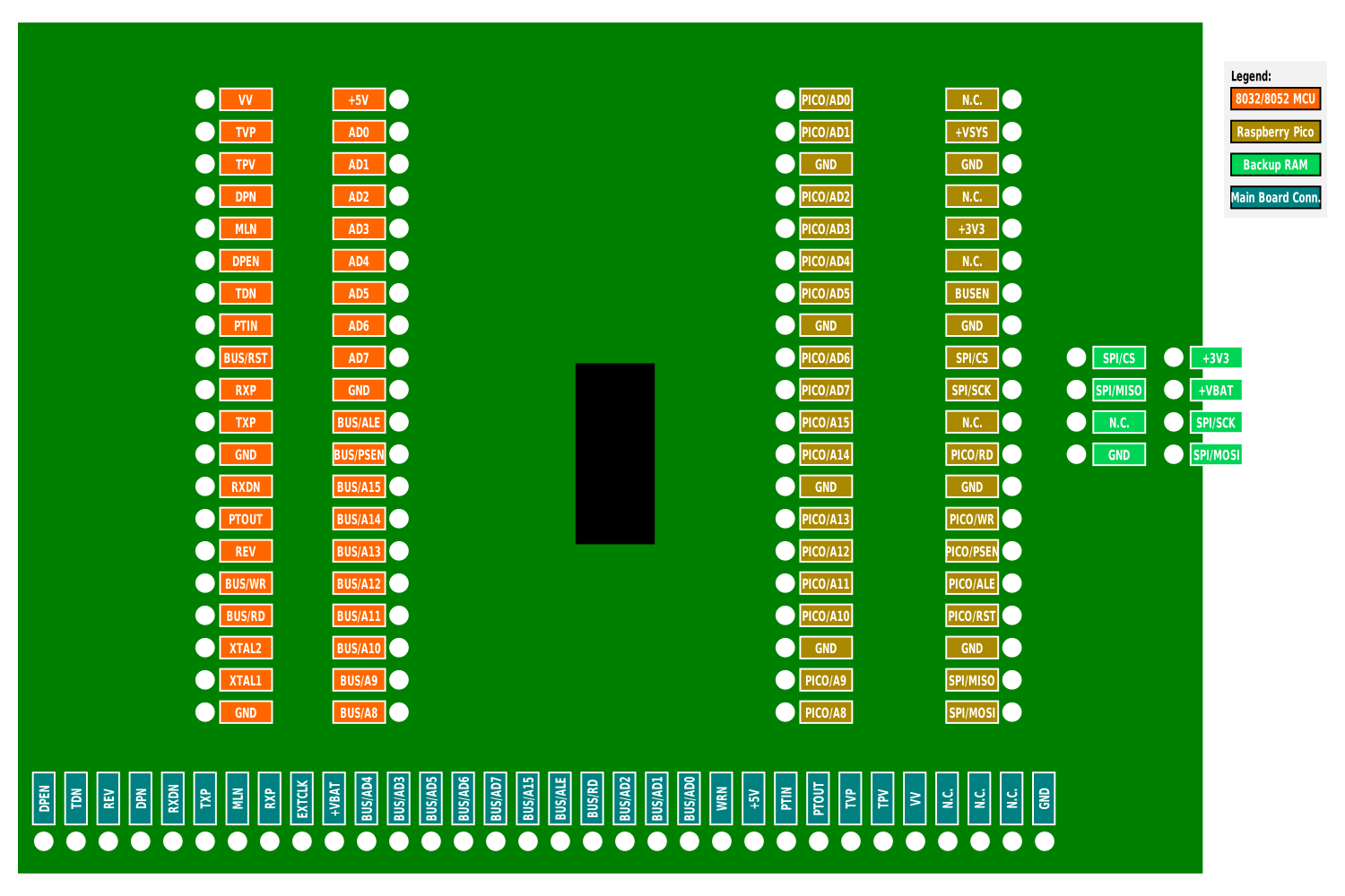
Solder the headers as shown in the pictures and populate the sockets with the corresponding chips.
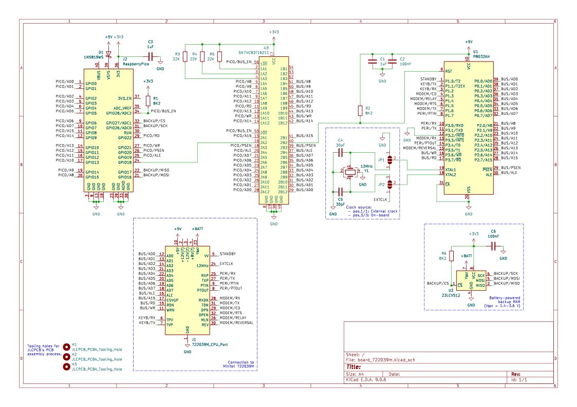
Use solder to close bridges JP1 and JP2 in one of the ways shown below, depending on the clock configuration of the Minitel's original CPU board:
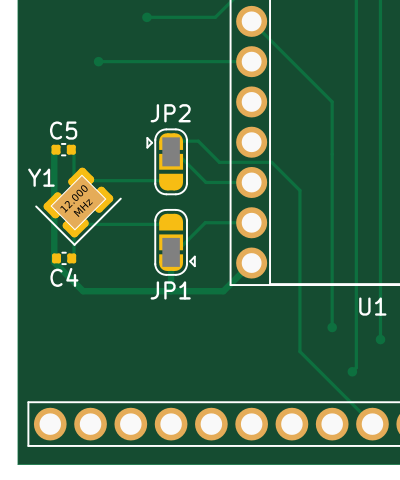 Position 1-1: Use external clock |
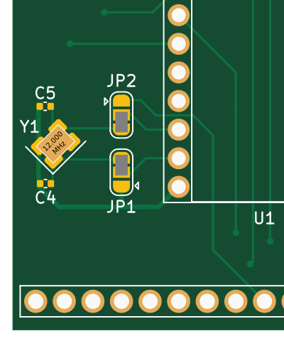 Position 3-3: Use on-board clock |
Choose position 3-3 only if the original CPU board has a crystal on it (see example pictures for what it looks like - note that it might be horizontal rather than vertical too). If no crystal is present in the original CPU board, choose position 1-1.
[!TIP] Some of the original design documents for this Minitel have been published at this page. The "M12 Description Technique 1988" file has a picture of the internal boards at page 18 and the original schematics at the end. The "Hardware M12" document has revised schematics that seem to better match the actual circuits in my Minitel.
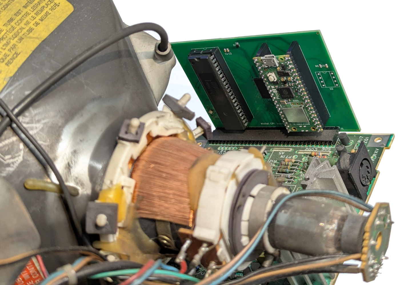
Installation is straightforward: pull the original CPU board out of the main board and replace it with the new board.
The Minitel 12's battery slot is located under the display (two 1.5V AA) and easily accessible without disassembling. See page 4 of the Minitel 12 manual. ↩
| Qty | Value | Footprint | References |
|---|---|---|---|
| 3 | 22K | Resistor_SMD:R_0402_1005Metric | R3, R4, R5 |
| 3 | 8K2 | Resistor_SMD:R_0603_1608Metric | R1, R2, R6 |
| 3 | JLCPCB_PCBA_Tooling_Hole | MountingHole:ToolingHole_1.152mm | H1, H2, H3 |
| 2 | 100nF | Capacitor_SMD:C_0603_1608Metric | C2, C6 |
| 2 | 1uF | Capacitor_SMD:C_0603_1608Metric | C1, C3 |
| 2 | 30pF | Capacitor_SMD:C_0402_1005Metric | C4, C5 |
| 2 | SolderJumper_3_Open | Jumper:SolderJumper-3_P1.3mm_Open_RoundedPad1.0x1.5mm | JP1, JP2 |
| 1 | 12MHz | Crystal:Crystal_SMD_3225-4Pin_3.2x2.5mm | Y1 |
| 1 | 1N5819WS | Diode_SMD:D_SOD-323 | D1 |
| 1 | 23LCV512 | Package_DIP:DIP-8_W7.62mm_Socket | U2 |
| 1 | 722039M_CPU_Port | Connector_PinHeader_2.54mm:PinHeader_1x32_P2.54mm_Vertical | J1 |
| 1 | P8032AH | Package_DIP:DIP-40_W15.24mm_Socket | U1 |
| 1 | RaspberryPico | ProjectFootprints:RaspberryPi_Pico_Common_THT | J2 |
| 1 | SN74CB3T16211 | Package_SO:TSSOP-56_6.1x14mm_P0.5mm | U3 |
fabio-d/minitel-native
Software and hardware tools to run native programs on the Minitel


makeo/PicoLoader
A cheap and easy to install modchip for the Nintendo GameCube!


AzonInc/Doorman
ESP32-S3 based Intercom Gateway (TCS / Koch / Niko / Scantron / Analogue Systems)

sd2psx/pcb
The PCB must be produced in 0.8mm thickness. Production files are provided under the "Releases" tab. These do not include the through-hole OLED module.

plinkysynth/plinky_public
a public release of the plinky sw and hw


o7-machinehum/Blackpants
Open blackpants.kicadpro for the active A523 schematic and PCB. It replaces the A33 hierarchy and uses AXP717C + AXP323 with 2GB LPDDR4.
It measures 93.2 × 67 mm and has 2 copper layers, 1.6 mm thick.
24 parts, built around the 23LCV512-E/P, SN74CB3T16211DL and 1N5819WS. The full list of its parts is on this page, with links to each part's symbol and footprint where PCBKit's library has them.
From the fabio-d/minitel-native repository on GitHub, at the commit this page was made from: the board is rom-emulation/board_722039m/board_722039m.kicad_pcb and its schematic rom-emulation/board_722039m/board_722039m.kicad_sch. PCBKit opens the board in the browser, with nothing to install.
Its repository publishes it under the CERN-OHL-W-2.0 licence: you may reuse it on that licence's terms (keep the author's notice, and for a copyleft licence share your changes alike).