8 layers45 × 45 mm

 ezer-soltani/HellKitty-Autonomous-Robot
Professional firmware and hardware design for an autonomous mobile robot using STM32G431 and FreeRTOS. Features Lidar perception, ToF safety algorithms, and PID motor control.
Projet Robot is an open-source printed circuit board by ezer-soltani, from the ezer-soltani/HellKitty-Autonomous-Robot repository on GitHub, published under the MIT licence. It is a 4-layer board of 54.1 × 57 mm with 88 parts on 77 nets, routed with 609 tracks and 113 vias.
It is built around the MP1475DJ-LF-P, ZXBM5210-SP and ADXL343BCCZ-RL, with the 1101M2S3CQE2 and BU33SD5WG-TR among its other parts. Its parts include 33 capacitors, 15 resistors, 5 diodes, 3 ICs and 2 connectors. It belongs with the robots and motor control boards and the STM32 boards of this library.







HellKitty is an industrial-grade autonomous combat robot engineered for high-speed table-top arena navigation ("Cat & Mouse" adversarial game logic). Designed from bare silicon up to deterministic application-layer control, the platform combines custom 4-layer power/signal mixed PCB hardware, bare-metal C peripheral drivers, and a preemptive FreeRTOS real-time architecture.
The robot executes simultaneous 360° laser perception (YDLIDAR X2 @ 115.2 kbps via DMA), 4-quadrant edge/void Time-of-Flight monitoring (VL53L0X @ 100 Hz), high-G collision detection (ADXL343 accelerometer), dual closed-loop velocity PID regulation (TIM2/TIM4 hardware encoder quadrature decoding @ 100 Hz), and dynamic state-machine tactical transitions under strict deterministic latency constraints.
+----------------------------------------------------------------------------------------------------+
|                                    HELLKITTY SYSTEM BENCHMARKS                                     |
+--------------------------+-------------------------------------------------------------------------+
| Core Frequency           | 170 MHz (ARM Cortex-M4F with hardware FPU & DSP instructions)           |
| Control Loop Frequency   | 100 Hz deterministic periodic execution (vTaskDelayUntil)               |
| Edge Safety Latency      | < 10 ms hardware-level emergency stop & auto-evacuation override        |
| LiDAR Data Stream        | Circular DMA buffer (1024 B) with zero-copy packet state-machine parser |
| Sensor Bus Topology      | I2C1 (Fast Mode 400 kHz) with FreeRTOS Mutex Priority Inheritance       |
| Dynamic Power Delivery   | 5.5V-12V input -> 5V @ 3A Buck (MP1475) -> 3.3V Low-Noise LDO (BU33SD5)  |
| Motor Control Drive      | Dual ZXBM5210-SP H-Bridges (3A peak, dynamic braking, 20 kHz PWM)       |
+--------------------------+-------------------------------------------------------------------------+The robot's firmware and hardware layers are decoupled through strict hardware abstraction and thread-safe real-time communication mechanisms:
graph TD
    %% Subsystem Grouping
    subgraph SENSORS["Perception & Telemetry Hardware"]
        LIDAR["YDLIDAR X2\n(360° 2D Laser Rangefinder)"]
        TOF["4x VL53L0X ToF\n(Quadrants: FL, FR, RL, RR)"]
        IMU["ADXL343\n(3-Axis Accelerometer)"]
        ENC["2x Quadrature Encoders\n(2048 CPR / Wheel)"]
        BT["HC-05 Bluetooth\n(Telemetry / Remote Shell)"]
    end

    subgraph HARDWARE_IF["STM32G431 Microcontroller Peripherals"]
        UART2_DMA["USART2 + Circular DMA\n(115200 baud, 1024B Buffer)"]
        I2C1_BUS["I2C1 Fast Mode (400kHz)\n(Addresses: 0x54, 0x56, 0x58, 0x5A, 0xA6)"]
        TIM_ENC["TIM2 (32-bit) & TIM4 (16-bit)\nHardware Encoder Interface Mode"]
        UART3_IT["USART3 RX Interrupt\n(Byte-by-byte parser)"]
        TIM3_PWM["TIM3 4-Channel PWM\n(20 kHz Motor Drive)"]
        GPIO_CTRL["GPIO Output / Status LEDs\n(XSHUT, Brake, Status LEDs)"]
    end

    subgraph RTOS_LAYER["FreeRTOS Preemptive Kernel"]
        MUTEX_I2C{{"xI2C1Mutex\n(Priority Inheritance)"}}
        MUTEX_UART{{"xUARTMutex\n(Thread-Safe Printf)"}}

TASK_SAFETY["vSafetyTask\n(Priority 3 | 100 Hz)\nEdge Void & Fault Protection"]The firmware uses FreeRTOS v10.3.1 with dynamic memory allocation, preemptive scheduling, and priority-inheritance mutexes to guarantee deterministic timing across all subsystems.
| Task Name | Priority | Periodicity / Trigger | Stack Size | Shared Resources / IPC | Functional Responsibility |
|---|---|---|---|---|---|
vControlTask | 4 (Highest) | 100 Hz (10 ms)vTaskDelayUntil | 512 words (2048 B) | Hardware Timers (TIM2/3/4), Target Speeds (target_speed_lin_x, target_speed_ang_z) | Reads wheel encoders, updates Runge-Kutta odometry, executes dual velocity PID loops with integral anti-windup, computes PWM duty cycles, and applies motor ramping. |
vSafetyTask | 3 (High) | 100 Hz (10 ms) Continuous Polling | 256 words (1024 B) | xI2C1Mutex, g_safety_override, STATUS_SOURIS_LED | Polls 4x VL53L0X ToF range registers. If distance to table surface exceeds 200 mm (void/cliff detected), asserts atomic override flag, cuts motor PWM, and commands automated pivot-and-reverse escape trajectory. |
vLidarTask | 2 (Normal) | 10 Hz (100 ms) (DMA Polled @ 100 Hz) | 512 words (2048 B) | huart2 Circular DMA buffer, xUARTMutex, g_target | Processes raw bytes from circular DMA, validates packet headers (0xAA 0x55) and XOR checksums, performs geometric angle correction, clusters contiguous obstacle points, and tracks closest target. |
vImuTask | 1 (Low) | 20 Hz (50 ms) Periodic Delay | 256 words (1024 B) | xI2C1Mutex, Strategy_ToggleRole() | Reads ADXL343 3-axis acceleration registers over I2C. Evaluates hardware SINGLE_TAP shock interrupt (>3.5G threshold) with 2000 ms debounce to switch between Cat (Predator) and Mouse (Prey) combat states. |
// Example: Thread-safe I2C bus acquisition with Priority Inheritance
if (xSemaphoreTake(xI2C1Mutex, portMAX_DELAY) == pdTRUE) {
    status = ADXL343_ReadAxes(&hi2c1, &accel_data);
    if (ADXL343_CheckShock(&hi2c1) && g_safety_override == 0) {
        shock_detected = 1;
    }
    xSemaphoreGive(xI2C1Mutex);
}xI2C1Mutex protects the single I2C peripheral shared between the 4x VL53L0X ToF rangefinders and the ADXL343 IMU. Priority inheritance guarantees that if the low-priority vImuTask holds the bus when vSafetyTask wakes up, vImuTask temporarily inherits Priority 3, preventing unbounded priority inversion.CNDTR counter offsets to parse complete frames asynchronously.g_safety_override decouples normal FSM navigation from the anti-fall maneuver. When asserted, vControlTask suspends trajectory setpoints until the robot returns to safe bounds.The robot is built around a custom 4-layer impedance-controlled PCB engineered in KiCad 9.0, optimized for high current density, low EMI, and clean power distribution.
| Layer | Name | Type | Copper Thickness | Dielectric Spacing | Functional Allocation |
|---|---|---|---|---|---|
| L1 | F.Cu (Top) | Signal | 35 µm (1 oz) | — | High-speed digital signals (SWD, USART, I2C, SPI), MCU breakout, sensor connectors. |
| — | Dielectric 1 | Prepreg (FR4) | — | 0.10 mm ((\varepsilon_r = 4.5)) | High capacitive coupling to ground plane. |
| L2 | In1.Cu (Inner 1) | Power / Plane | 35 µm (1 oz) | — | Continuous Solid Ground Plane (GND) for unbroken return current paths and EMI reduction. |
| — | Dielectric 2 | Core (FR4) | — | 1.24 mm ((\varepsilon_r = 4.5)) | Structural core isolation. |
| L3 | In2.Cu (Inner 2) | Power / Plane | 35 µm (1 oz) | — | Power Distribution Plane (PWR): Split polygon pours for +5V, +3.3V, and VBAT. |
| — | Dielectric 3 | Prepreg (FR4) | — | 0.10 mm ((\varepsilon_r = 4.5)) | High capacitive coupling to bottom layer. |
| L4 | B.Cu (Bottom) | Signal | 35 µm (1 oz) | — | High-current motor H-bridge power routing, thermal relief dissipation, and test points. |
| Subsystem | Component / IC | Interface | Specifications & Operational Role |
|---|---|---|---|
| MCU | STM32G431CBU6 (UFQFPN48) | SWD / STDC14 | ARM Cortex-M4F @ 170 MHz, 128 KB Flash, 32 KB SRAM, hardware FPU/DSP, CORDIC math unit. |
| Step-Down Buck | MPS MP1475DJ-LF-P | Switching Reg | 500 kHz synchronous buck converter converting 2S/3S LiPo battery (7.4V–11.1V) to a stable 5.0V @ 3.0A rail. |
| Low-Noise LDO | ROHM BU33SD5WG-TR | Linear Reg | High PSRR, ultra-low dropout linear regulator stepping down 5.0V to 3.3V for MCU core and analog peripherals. |
| Motor Drivers | 2x Diodes Inc. ZXBM5210-SP | TIM3 PWM / GPIO | Reversible H-Bridge drivers (3V–18V, 0.85A continuous, 3.0A peak, SOIC-8EP) with dynamic braking and cross-conduction protection. |
| LiDAR Sensor | YDLIDAR X2 | USART2 + DMA | 360° 2D triangulation laser rangefinder (8 Hz rotational scan frequency, 0.12m–8.0m range, 3 kHz sample rate). |
| Cliff / ToF Array | 4x STMicroelectronics VL53L0X | I2C1 + 4x XSHUT | Time-of-Flight ranging sensors dynamically re-addressed (0x54, 0x56, 0x58, 0x5A) for four-corner table edge monitoring. |
| IMU / Shock | Analog Devices ADXL343BCCZ | I2C1 + INT2 | 3-axis ultra-low power digital accelerometer configured for SINGLE_TAP interrupt capture (>3.5G collision detection). |
| Encoders | 2x Quadrature Optical/Magnetic | TIM2 / TIM4 | Dual-channel differential quadrature encoder feedback (2048 counts per wheel revolution in 4x mode). |
| Telemetry / Comms | HC-05 Bluetooth Module | USART3 @ 9600bd | Bidirectional UART telemetry bridge for real-time telemetry streaming and remote state control. |
The complete schematic design is partitioned into modular hierarchical sheets inside hardware/:
| Schematic Sheet | Source File | Description |
|---|---|---|
| Root Top Sheet | Projet_Robot.kicad_sch | Top-level interconnections, hierarchical bus links, and module connectors. |
| MCU & Clocks | µcontrolleur.kicad_sch | STM32G431 pinout, STDC14 debug connector, external 8 MHz crystal, bypass capacitors, and status LEDs. |
| Power Regulators | regulateurs.kicad_sch | MP1475 buck regulator, BU33SD5 LDO, LC output filtering, reverse-polarity protection, and slide power switch. |
| Sensor Array | capteur.kicad_sch | 4x VL53L0X ToF connectors with XSHUT lines, ADXL343 accelerometer layout, and YDLIDAR / HC-05 headers. |
| Motor Driver 1 & 2 | moteur1.kicad_sch | Dual ZXBM5210-SP H-Bridges, flyback suppression capacitors, test points, and JST-XH encoder/motor connectors. |
The LiDAR stream transmits continuous variable-length point frames at 115200 baud over USART2. To eliminate CPU byte-by-byte interrupts, DMA operates in circular ring-buffer mode (LIDAR_DMA_BUFFER_SIZE = 1024):
// Zero-overhead ring buffer processing in vLidarTask
uint16_t pos = LIDAR_DMA_BUFFER_SIZE - __HAL_DMA_GET_COUNTER(huart2.hdmarx);
if (pos != old_pos) {
    if (pos > old_pos) {
        ydlidar_process_data(&lidar_dma_buffer[old_pos], pos - old_pos);
    } else {
        ydlidar_process_data(&lidar_dma_buffer[old_pos], LIDAR_DMA_BUFFER_SIZE - old_pos);
        if (pos > 0) ydlidar_process_data(&lidar_dma_buffer[0], pos);
    }
    old_pos = pos;
}0xAA 0x55.CT), Sample Count (LSN), First Sample Angle (FSA), and Last Sample Angle (LSA).All four VL53L0X Time-of-Flight sensors power up with the identical default I2C address (0x29 / 0x52). The custom driver performs a deterministic hardware-timed bootstrap:
sequenceDiagram
    participant MCU as STM32G431 (Master)
    participant T1 as TOF1 (Front-Right)
    participant T2 as TOF2 (Front-Left)
    participant T3 as TOF3 (Rear-Left)
    participant T4 as TOF4 (Rear-Right)

    Note over MCU,T4: Reset Phase: Drive all XSHUT pins LOW
    MCU->>T1: XSHUT1 = 0
    MCU->>T2: XSHUT2 = 0
    MCU->>T3: XSHUT3 = 0
    MCU->>T4: XSHUT4 = 0
    MCU->>MCU: Delay 20ms

    Note over MCU,T1: Stage 1: Initialize TOF 1
    MCU->>T1: XSHUT1 = 1 (Wake up)
    MCU->>T1: Write Reg 0x8A -> Re-address to 0x54
    MCU->>T1: Load Calibration & Start Continuous Mode

    Note over MCU,T2: Stage 2: Initialize TOF 2
    MCU->>T2: XSHUT2 = 1 (Wake up)
    MCU->>T2: Write Reg 0x8A -> Re-address to 0x56
    MCU->>T2: Load Calibration & Start Continuous Mode
              +-------------------------------------------------------------+
              |                      STRATEGY FSM                           |
              |       (SEARCH -> ATTACK [Cat] / FLEE [Mouse])               |
              +-------------------------------------------------------------+
                                   |                     |
                      v_lin (target_speed_lin_x)    v_ang (target_speed_ang_z)
                                   |                     |
                                   v                     v
              +-------------------------------------------------------------+
              |                DIFFERENTIAL KINEMATICS                      |
              |  ω_L = (v_lin - v_ang * L/2) / R                            |
              |  ω_R = (v_lin + v_ang * L/2) / R                            |
              +-------------------------------------------------------------+
                         |                                  |
                   Target ω_L                         Target ω_R
                         |                                  |
                         v                                  v
              +--------------------+             +--------------------+
              |  PID LEFT (Motor2) |             | PID RIGHT (Motor1) |
              |  Kp=5.0, Ki=20.0   |             | Kp=5.0, Ki=20.0    |
              |  Anti-Windup Clamped|             | Anti-Windup Clamped|
              +--------------------+             +--------------------+
                         |                                  |
PWM_Duty_L PWM_Duty_R$$\text{Output}(t) = K_p \cdot e(t) + K_i \int_0^t e(\tau),d\tau + K_d \frac{de(t)}{dt}$$
To prevent integrator windup during motor saturation or abrupt stops: $$\text{Integral}{\text{clamped}} = \max\left(-\text{Max}{\text{int}}, \min\left(\text{Max}_{\text{int}}, \text{Integral} + e(t) \cdot \Delta t\right)\right)$$
Wheel speeds (\omega_L, \omega_R) are converted to linear displacement at (\Delta t = 10,\text{ms}): $$v_{\text{robot}} = \frac{v_R + v_L}{2}, \quad \omega_{\text{robot}} = \frac{v_R - v_L}{L_{\text{track}}}$$ $$\Delta \theta = \omega_{\text{robot}} \cdot \Delta t, \quad \theta_{\text{mid}} = \theta_k + \frac{\Delta \theta}{2}$$ $$x_{k+1} = x_k + v_{\text{robot}} \cdot \cos(\theta_{\text{mid}}) \cdot \Delta t$$ $$y_{k+1} = y_k + v_{\text{robot}} \cdot \sin(\theta_{\text{mid}}) \cdot \Delta t$$ $$\theta_{k+1} = \theta_k + \Delta \theta \pmod{2\pi}$$
arm-none-eabi-gcc (v10.3 or higher)STM32CubeProgrammer, openocd, or st-flashpyserial, matplotlib, numpy)File -> Import -> Existing Projects into Workspace.firmware/ directory and click Finish.Release or Debug).Ctrl+B).Ctrl+F11).# 1. Clone the repository
git clone https://github.com/ezer-soltani/HellKitty-Autonomous-Robot.git
cd HellKitty-Autonomous-Robot
# 2. Flash binary via OpenOCD with ST-Link
openocd -f interface/stlink.cfg -f target/stm32g4x.cfg \
-c "program firmware/Debug/Firmware_Robot.elf verify reset exit"
# Alternatively, using STM32CubeProgrammer CLI:
STM32_Programmer_CLI -c port=SWD -w firmware/Debug/Firmware_Robot.bin 0x08000000 -v -rstA custom Python polar visualizer is included in scripts/visualizer.py for real-time laser point-cloud streaming over serial:
# Install visualizer dependencies
pip install pyserial matplotlib numpy

# Run the real-time visualizer (adjust port to your serial device, e.g. COM3 or /dev/ttyUSB0)
python scripts/visualizer.py
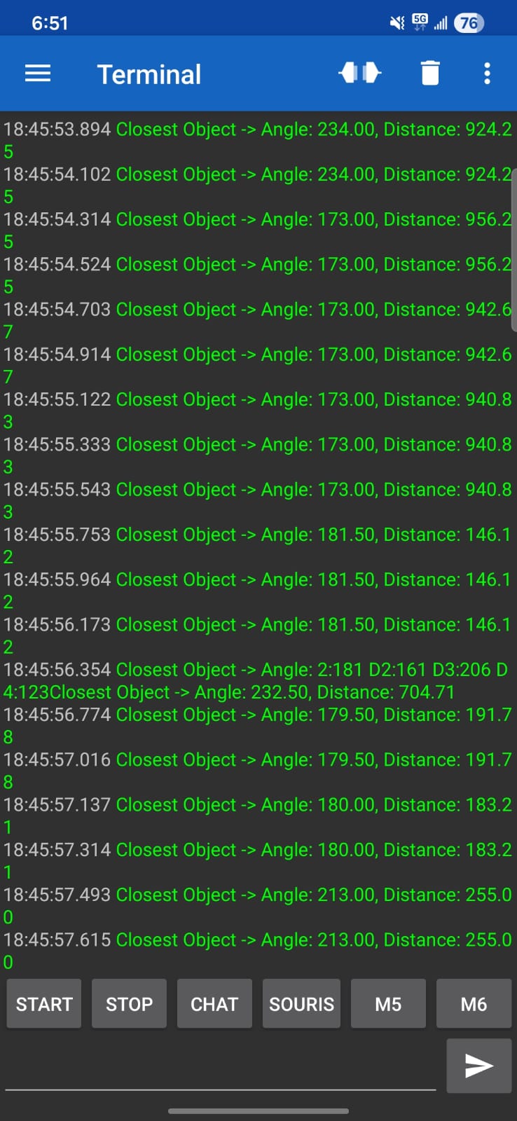
Connect via Bluetooth terminal (HC-05 @ 9600 baud) or ST-Link Virtual COM Port (USART1 @ 115200 baud):
| Command String | Firmware Handler | Action Performed |
|---|---|---|
START\n | Strategy_SetEnabled(1) | Enables motor outputs and activates the Strategy FSM. |
STOP\n | Strategy_SetEnabled(0) | Emergency stop: forces motor PWM to 0% and clears setpoints. |
CHAT\n | Strategy_SetRole(ROLE_CHAT) | Manually sets combat mode to Cat (Predator). Green LED on. |
SOURIS\n | Strategy_SetRole(ROLE_SOURIS) | Manually sets combat mode to Mouse (Prey). Red LED on. |
HellKitty-Autonomous-Robot/
├── firmware/                       # Embedded STM32 Firmware
│   ├── Core/
│   │   ├── Drivers/                # Custom Bare-Metal / HAL Component Drivers
│   │   │   ├── hc-05_bluetooth.c/h # Bluetooth command interpreter & telemetry
│   │   │   ├── imu.c/h             # ADXL343 I2C driver & shock interrupt config
│   │   │   ├── lidar.c/h           # YDLIDAR X2 DMA parser & object clustering
│   │   │   ├── motor.c/h           # H-Bridge PWM & hardware encoder interface
│   │   │   ├── odometry.c/h        # Runge-Kutta differential drive odometry
│   │   │   ├── pid.c/h             # Closed-loop velocity PID with anti-windup
│   │   │   └── tof.c/h             # 4x VL53L0X dynamic I2C bootstrap driver
│   │   ├── Inc/                    # Application Headers & Peripheral Configs
│   │   │   ├── FreeRTOSConfig.h    # Kernel configuration (Preemption, Heap, Priorities)
│   │   │   ├── main.h              # Pin definitions & hardware clock mappings
│   │   │   └── strategy.h          # FSM state declarations & game logic
│   │   └── Src/                    # RTOS Tasks & HAL Peripheral Initialization
│   │       ├── app_freertos.c      # FreeRTOS task implementations & mutex definitions
│   │       ├── main.c              # System initialization & clock tree setup (170MHz)
│   │       └── strategy.c          # Tactical FSM (SEARCH / ATTACK / FLEE)
│   ├── Drivers/                    # STMicroelectronics CMSIS & G4 HAL Drivers
│   ├── Middlewares/                # FreeRTOS Real-Time Kernel Source Code
│   ├── Firmware_Robot.ioc          # STM32CubeMX Hardware Configuration Project
│   └── STM32G431CBUX_FLASH.ld      # GCC Linker Script (Memory Map layout)
├── hardware/ # KiCad 9.0 Electronic CAD ProjectDeveloped at ENSEA (Graduate School of Electrical and Computer Engineering) within the Electronics & Embedded Systems (ESE) department:
This project is licensed under the MIT License — see the LICENSE file for complete details.
| Qty | Value | Footprint | References |
|---|---|---|---|
| 16 | 100n | Capacitor_SMD:C_0402_1005Metric | C1, C5, C6, C7, C9, C11, C15, C16, C17, C21, C22, C23, C24, C25, C32, C33 |
| 8 | 1u | Capacitor_SMD:C_0603_1608Metric | C12, C13, C26, C27, C28, C29, C30, C31 |
| 7 | TestPoint | TestPoint:TestPoint_Pad_D1.5mm | TP_PWM_1_2, TP1, TP2, TP3, TP6, TP7, TP8 |
| 5 | Conn_01x06 | Connector_PinSocket_2.54mm:PinSocket_1x06_P2.54mm_Vertical | Bluetooth1, TOF1, TOF2, TOF3, TOF4 |
| 5 | LED_Small | LED_SMD:LED_0603_1608Metric | D1, D2, D3, D4, D5 |
| 4 | MountingHole_Pad | MountingHole:MountingHole_3.2mm_M3_Pad_Via | H1, H2, H3, H4 |
| 3 | 22u | Capacitor_SMD:C_0805_2012Metric | C14, C18, C20 |
| 2 | 100K | Resistor_SMD:R_0603_1608Metric | R7, R9 |
| 2 | 10p | Capacitor_SMD:C_0402_1005Metric | C3, C4 |
| 2 | 2k2 | Resistor_SMD:R_0603_1608Metric | R1, R2 |
| 2 | 600 | Resistor_SMD:R_0603_1608Metric | R3, R4 |
| 2 | Conn_01x06 | Connector_JST:JST_XH_S6B-XH-A_1x06_P2.50mm_Horizontal | Motor1, Motor2 |
| 2 | SW_Push | KiCad:SW Push 1P1T NO 6x6mm H9.5mm | ch/sou1, SW1 |
| 2 | ZXBM5210-SP | Package_SO:Diodes_SO-8EP | M1, M2 |
| 1 | 10K | Resistor_SMD:R_0603_1608Metric | R20 |
| 1 | 10k | Resistor_SMD:R_0603_1608Metric | R17 |
| 1 | 10n | Capacitor_SMD:C_0603_1608Metric | C8 |
| 1 | 10u | Capacitor_SMD:C_0603_1608Metric | C10 |
| 1 | 1101M2S3CQE2 | KiCad:1101M2S3QE2 | S1 |
| 1 | 15p | Capacitor_SMD:C_0402_1005Metric | C19 |
| 1 | 16MHz | Crystal:Crystal_SMD_EuroQuartz_MT-4Pin_3.2x2.5mm | Y1 |
| 1 | 16k | Resistor_SMD:R_0603_1608Metric | R11 |
| 1 | 1k6 | Resistor_SMD:R_0603_1608Metric | R14 |
| 1 | 20k | Resistor_SMD:R_0603_1608Metric | R10 |
| 1 | 2k3 | Resistor_SMD:R_0603_1608Metric | R5 |
| 1 | 39n | Inductor_SMD:L_0603_1608Metric | L1 |
| 1 | 40k2 | Resistor_SMD:R_0603_1608Metric | R13 |
| 1 | 4k5 | Resistor_SMD:R_0603_1608Metric | R6 |
| 1 | 4u7 | Inductor_SMD:L_APV_ANR5040 | L2 |
| 1 | 4u7 | Capacitor_SMD:C_0603_1608Metric | C2 |
| 1 | 7K68 | Resistor_SMD:R_0603_1608Metric | R12 |
| 1 | ADXL343BCCZ-RL | Package_LGA:LGA-14_3x5mm_P0.8mm_LayoutBorder1x6y | IC1 |
| 1 | BU33SD5WG-TR | Package_SO:TSOP-5_1.65x3.05mm_P0.95mm | PS1 |
| 1 | Conn_01x05 | Connector_JST:JST_XH_B5B-XH-A_1x05_P2.50mm_Vertical | Lidar1 |
| 1 | Conn_Battery_Cell | Connector_JST:JST_EH_B2B-EH-A_1x02_P2.50mm_Vertical | J1 |
| 1 | Conn_ST_STDC14 | Connector_PinHeader_1.27mm:PinHeader_2x07_P1.27mm_Vertical_SMD | J11 |
| 1 | L | KiCad:logo hello | HelloKitty |
| 1 | LOGO | LOGO | G*** |
| 1 | MP1475DJ-LF-P | Package_TO_SOT_SMD:TSOT-23-8_HandSoldering | IC2 |
| 1 | STM32G431CBUx | Package_DFN_QFN:QFN-48-1EP_7x7mm_P0.5mm_EP5.6x5.6mm | U1 |

flexdrt/2425_ESE_Projet_StealthKitty
Ce projet est réalisé dans le cadre de la dernière année de la filière électronique et systèmes embarqués (ESE) de l'ENSEA.


HOSTEER/ESE2024
Activer doxygen dans les propriétés du projet -> général C/C++, tuto doxygen https://www.youtube.com/watch?v=GC9Xy7nLxyw

exysta/2425_ESE_Projet_TagBot
Vous vous trouvez actuellement dans le projet TagBot (ou robot chat), qui s'intègre à un projet de classe où chaque équipe doit concevoir un robot.

MohamedBenabdelhadi/2425_ESE_Projet_V-NOM
Mohamed Benabdelhadi_Nouhaila Faris_Oliver Belliard_Valerian Priou

Manassehalt/2425_ESE_Projet_Torero
Projet de 3ème année d'ESE réalisé par : - JACQUOT Nolan - GUIFFAULT Gabriel - BOULOT Paul - THOMAR Jean-Philippe

It measures 54.1 × 57 mm and has 4 copper layers, 1.6 mm thick.
88 parts, built around the MP1475DJ-LF-P, ZXBM5210-SP, ADXL343BCCZ-RL and 1101M2S3CQE2. The full list of its parts is on this page, with links to each part's symbol and footprint where PCBKit's library has them.
From the ezer-soltani/HellKitty-Autonomous-Robot repository on GitHub, at the commit this page was made from: the board is hardware/Projet_Robot.kicad_pcb and its schematic hardware/Projet_Robot.kicad_sch. PCBKit opens the board in the browser, with nothing to install.
Its repository publishes it under the MIT licence: you may reuse it on that licence's terms (keep the author's notice, and for a copyleft licence share your changes alike).