
2 layers38.1 × 38.1 mm
SIM868
vul-os/sirboard
Open hardware: 107 KiCad PCB designs — SMD-to-THT breakout adapters, ATTiny/ATMega/ESP development boards, and a 39-part sensor line on a common JST-SH connector.
73 parts56Apache-2.0

 eydam-prototyping/GPS-Tracker
GPS Tracker is an open-source printed circuit board by eydam-prototyping, from the eydam-prototyping/GPS-Tracker repository on GitHub. It is a 2-layer board of 59.4 × 47.2 mm with 6 parts on 72 nets, routed with 36 tracks and 0 vias.
It is built around the LXES15AAA1-153. Its parts include 2 capacitors, 1 resistor, 1 IC, 1 diode and 1 connector. It belongs with the radio and wireless boards of this library.
This project involves developing a GPS tracker using a Raspberry Pi Pico (RP2040) and a SIM7040G module with a built-in GPS. The device will publish its location and cell data to AWS IoT Core every 5 minutes.
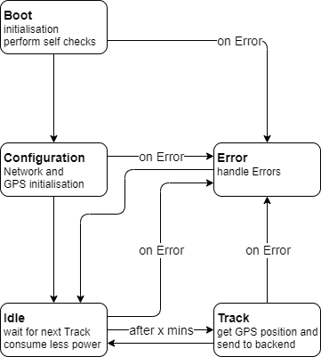
Implement power-saving techniques, especially in the Idle State, to extend battery life.
| Qty | Value | Footprint | References |
|---|---|---|---|
| 2 | NC | Capacitor_SMD:C_0805_2012Metric_Pad1.18x1.45mm_HandSolder | C1, C2 |
| 1 | 0 | Resistor_SMD:R_0805_2012Metric_Pad1.20x1.40mm_HandSolder | R1 |
| 1 | Conn_Coaxial | Connector_Coaxial:SMA_Molex_73251-2120_EdgeMount_Horizontal | J1 |
| 1 | LXES15AAA1-153 | Diode_SMD:D_0402_1005Metric | D1 |
| 1 | ~ | SIMCOM_Modules:SIMCOM7600E | U1 |
vul-os/sirboard
Open hardware: 107 KiCad PCB designs — SMD-to-THT breakout adapters, ATTiny/ATMega/ESP development boards, and a 39-part sensor line on a common JST-SH connector.

wangyeee/OpenHardware
Collections of hardware design related to my drone project.

CDonohoe-Designs/EdgeLink_S3_Cellular
EdgeLink S3 Cellular is a four-layer embedded hardware platform combining an ESP32-S3 controller, SIM7080G cellular/GNSS modem, USB-C, battery power management and environmental/motion sensing.

kenyattaejones32-boop/AQM
Open-source hardware design for OpenHAP, an ESP32-based air quality monitor with CO sensing, thermistor temperature input, USB-C charging, and cellular data upload.

kenyattaejones32-boop/Gasmat_Gateway
KiCad 8 hardware design for the Gasmat Gateway board (Geviton).


It measures 59.4 × 47.2 mm and has 2 copper layers, 1.6 mm thick.
6 parts, built around the LXES15AAA1-153. The full list of its parts is on this page, with links to each part's symbol and footprint where PCBKit's library has them.
From the eydam-prototyping/GPS-Tracker repository on GitHub, at the commit this page was made from: the board is pcb/gps-tracker.kicad_pcb and its schematic pcb/gps-tracker.kicad_sch. PCBKit opens the board in the browser, with nothing to install.
Its repository states no licence, so its author keeps all rights: ask eydam-prototyping before reusing the design.