2 layers96 × 76 mm
Wb2
falseywinchnet/hf-active-antennas
Open-hardware HF receive-antenna amplifiers: zero-flux loop amp, loop LNA, mini-whip. LTspice models, KiCad boards, JLCPCB packages. see license
167 parts

 EVtivity/evtivity-ev-tester3
An open-source, EV-side charging simulator. It emulates an electric vehicle so you can test AC charging stations (EVSE) and CSMS backends on the bench, without a real car.
Ac tester production is an open-source printed circuit board by EVtivity, from the EVtivity/evtivity-ev-tester repository on GitHub. It is a 2-layer board of 100 × 64 mm with 68 parts on 29 nets, routed with 347 tracks and 94 vias.
It is built around the AP2112K-3.3, TPS26621DRC and BAT54WS, with the PMEG2005AEA, 1N4148WS and CDSOD323-T15C among its other parts. Its parts include 19 resistors, 8 capacitors, 6 diodes, 5 transistors and 5 connectors.


An open-source, EV-side charging simulator. It emulates an electric vehicle so you can test AC charging stations (EVSE) and CSMS backends on the bench, without a real car.
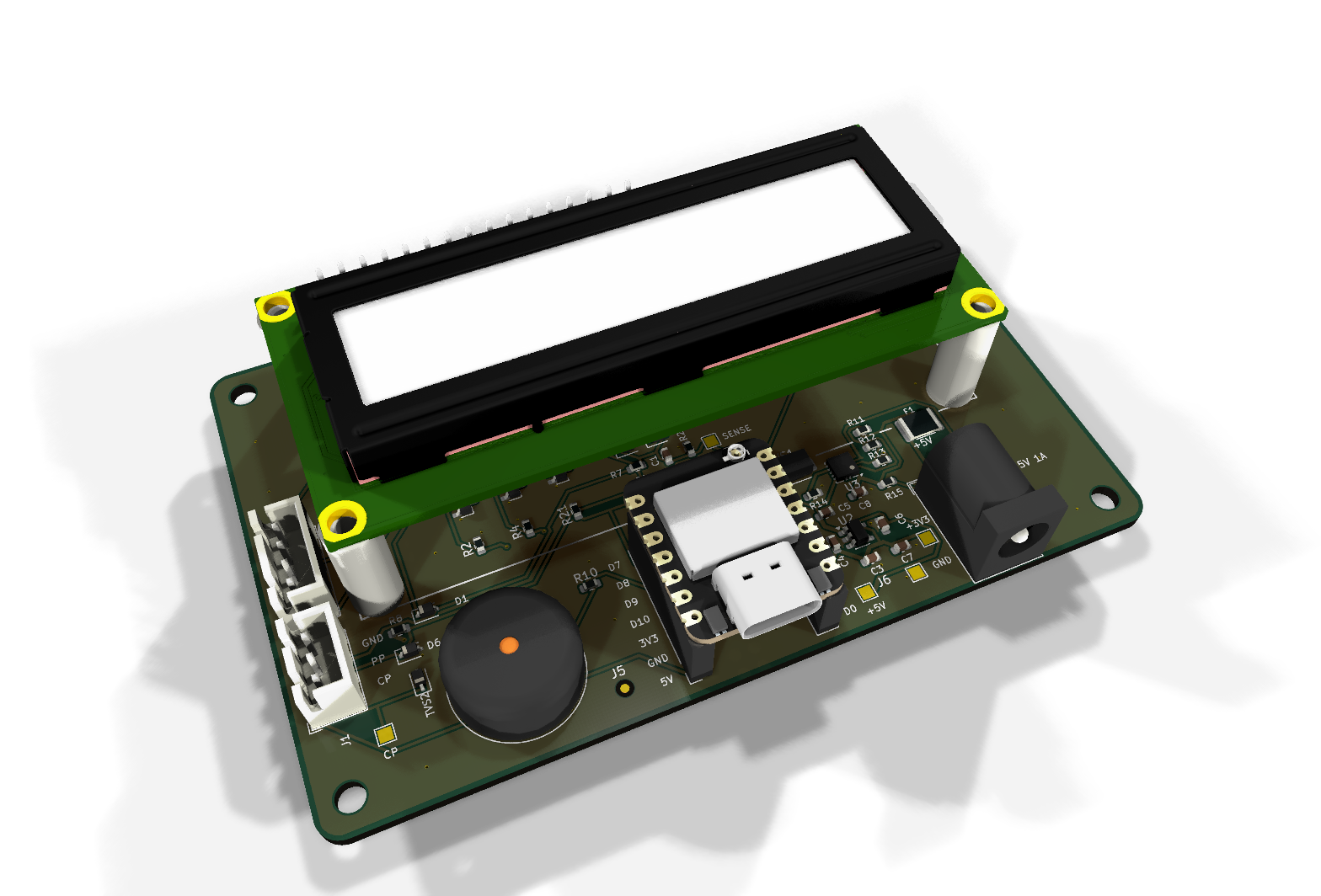
Built around a Seeed XIAO ESP32-S3 on a small carrier PCB, it drives the SAE J1772 / IEC 61851-1 Control Pilot line through states A, B, and C, reads the charger's offered current from the CP PWM, and reports proximity. A charger sees a full session lifecycle: vehicle detect, transaction start, Charging status, offered current, transaction stop.
Demos: the tester running in its 3D-printed enclosure, with more on the EVtivity YouTube channel.
This is a low-voltage signaling tester. It does not draw current or measure energy. When you enter Charging the EVSE closes its contactor and opens a session, but because no real load is connected the charger's meter reads near zero. That is expected and by design. The LCD "offered" and "kW" values are computed from the pilot duty (what the charger advertises), not measured from current flow.
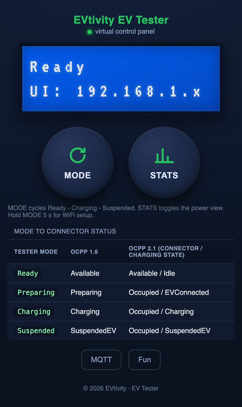
Once on WiFi, the device serves a login-protected web control panel that mirrors the LCD and drives the session from a browser - the same MODE/STATS controls, the mode-to-OCPP status mapping, and a live MQTT panel. Hold MODE for 5 s (physical or on-screen) to open the WiFi/MQTT setup access point.
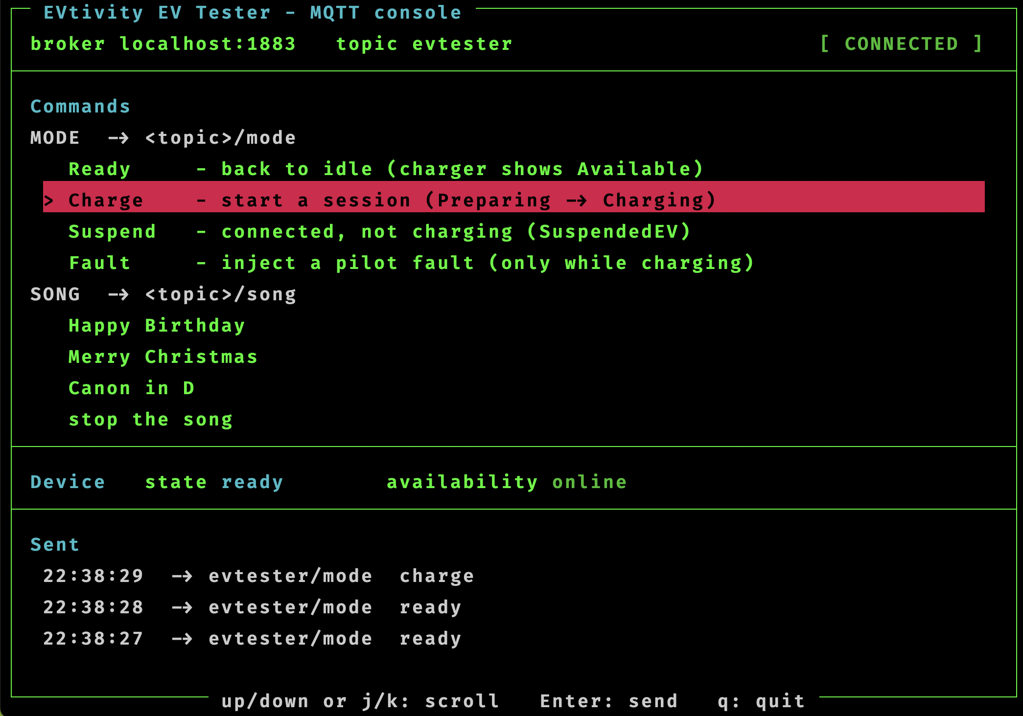
For automation, the tester also connects to an MQTT broker, taking mode and song
commands while publishing its live state (retained) and availability (last-will). The repo
ships a terminal console client, mqtt-test.py - run it, point it at your broker and topic,
and scroll the commands with the arrow keys. See USER-MANUAL.html for the full command
reference and how to run a local broker.
An optional printed case houses the board, LCD, and J1772 inlet. It prints in three parts and
fastens together with M3 screws. STL files are in enclosure/, and there is a
build demo video.
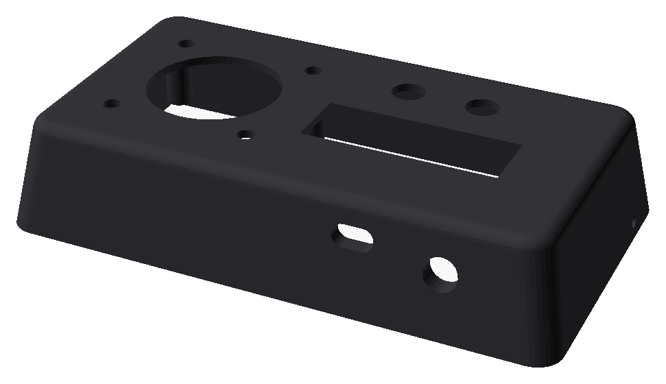 | 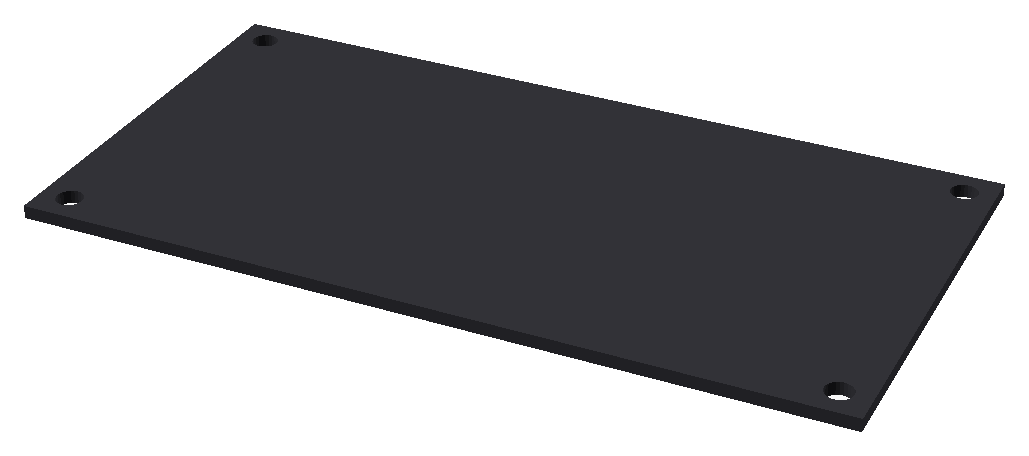 | 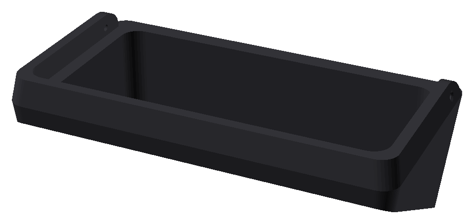 |
| Top front cover: inlet, LCD, and button cutouts | Bottom base plate | Mount mounting bracket |
| Path | What it is |
|---|---|
firmware/ac_tester/ | The Arduino firmware for the XIAO ESP32-S3 (flash this). |
jlcpcb/ | The KiCad design plus ready-to-order Gerbers, BOM, and pick-and-place files. |
docs/HARDWARE.md | Build guide: parts list, connector pinout, and how to wire a J1772 inlet. |
enclosure/ | 3D-printable case (STL files). |
USER-MANUAL.html | Full user manual (modes, buttons, LCD, web UI, MQTT). |
mqtt-test.py | Terminal MQTT console client for driving the tester over a broker. |
AC-tester-BOM-amazon.html | Buy-links list for the parts you add yourself (the ones JLCPCB does not assemble). |
The jlcpcb/ folder has everything to order the board fully assembled from
JLCPCB:
jlcpcb/ac-tester-gerbers.zip to fabricate the bare PCB.jlcpcb/ac-tester-bom.csv (BOM) and jlcpcb/ac-tester-cpl.csv
(component placement).JLCPCB assembles the SMD parts on the board. The modules and hardware you add yourself - the Seeed XIAO ESP32-S3, the 16x2 I2C LCD, the U.FL antenna, the J1772 inlet, and the case hardware
AC-tester-BOM-amazon.html.To open or modify the design, use KiCad and
jlcpcb/ac-tester-production.kicad_pro. jlcpcb/ac-tester-schematic.pdf and
jlcpcb/ac-tester-3d-full.step are provided for reference and mechanical fit.
The board is only the carrier. You also add a Seeed XIAO ESP32-S3, a 16x2 I2C LCD, a U.FL antenna, and a J1772 inlet (the vehicle-side socket the charger plugs into).
The one connection people ask about: this tester emulates the vehicle, so a charger's connector plugs into a J1772 inlet, and you wire that inlet's three signal lines to connector J1 on the board:
| J1772 inlet | Board J1 |
|---|---|
| Control Pilot (CP) | CP |
| Proximity (PP) | PP |
| Protective Earth / Ground | GND |
The inlet's AC power pins are left unconnected. Full parts list, pinout, and step-by-step
assembly are in docs/HARDWARE.md.
Target: Seeed XIAO ESP32-S3, Arduino-ESP32 core 3.x.
Using arduino-cli:
arduino-cli core install esp32:esp32
arduino-cli compile --fqbn esp32:esp32:XIAO_ESP32S3 firmware/ac_tester
arduino-cli upload  --fqbn esp32:esp32:XIAO_ESP32S3 -p <your-port> firmware/ac_tester
Or open firmware/ac_tester/ac_tester.ino in the Arduino IDE, select the XIAO ESP32-S3
board, and upload.
The WiFi antenna is required. The XIAO ESP32-S3 has no onboard antenna. Clip on the external U.FL/IPEX antenna or WiFi will not work. WiFi is optional, though: with no credentials the device runs fully as a tester and you can hold MODE for 5 s to open a setup access point and configure WiFi/MQTT from your phone.
Weak WiFi /
AUTH_EXPIREon early XIAO ESP32-S3 boards. XIAO ESP32-S3 units made before August 2025 have a marginal RF front end: at full TX power the signal is distorted and the access point drops the connection withReason 2 (AUTH_EXPIRE), even with the antenna on and the router nearby. The firmware already works around this by capping the WiFi TX power to 15 dBm (esp_wifi_set_max_tx_power), which restores a strong, reliable connection. Leave that in place; it is harmless on newer boards. This is a known Seeed issue - see Seeed's XIAO ESP32-S3 WiFi notes.
If the boot splash and jingle ever play twice. This is an interrupt-watchdog reset (
TG1WDT_SYS_RST) during WiFi start-up, and it comes from the Arduino ESP32 core rather than this sketch. The core ships its prebuilt WiFi libraries withCONFIG_ESP_WIFI_IRAM_OPTandCONFIG_ESP_WIFI_RX_IRAM_OPTturned off (ESP-IDF turns both on by default) to save about 5 KB of IRAM, which leaves the WiFi driver's interrupt path running from flash. Any flash write disables the instruction cache while it runs, and if the WiFi hardware raises an interrupt in that window the handler faults and the watchdog resets the board. In short, on this platform a flash write while WiFi is running can reset the board. It is not the power supply, and it is not the display. The firmware handles it two ways: it shuts the radio down before every settings write, and it brings the WiFi PHY up in the first 20 ms of boot so the one write it cannot move (the radio's own calibration data, stored once after a first flash or a core upgrade) happens before the screen and the fanfare. If you add code to this firmware, never write to flash while WiFi is up - use the same pattern asstopWifiForFlash(). A complete fix requires building with ESP-IDF andCONFIG_ESP_WIFI_IRAM_OPT=y, which is not settable from the Arduino IDE orarduino-cli.
See USER-MANUAL.html for the modes, buttons, web UI, and MQTT command reference.
This tester keeps everything at the low-voltage EV-signaling side of J1772, so it is safe to build and use on the bench. It is not a DC fast-charge tester and does not handle mains or high-voltage DC.
Dual-licensed by component: firmware under Apache-2.0, hardware under CERN-OHL-P-2.0.
See LICENSE for details. You are free to build, modify, and sell the hardware
and firmware; the EVtivity name and logo are not covered by these licenses.
Issues and pull requests are welcome. See CONTRIBUTING.md.
| Qty | Value | Footprint | References |
|---|---|---|---|
| 5 | 100k | R_0603_1608Metric | R2, R4, R15, R20, R21 |
| 5 | 10k | R_0603_1608Metric | R14, R16, R17, R18, R19 |
| 5 | 2N7002 | SOT-23 | Q1, Q2, Q5, Q6, Q7 |
| 4 | LCD | MountingHole_2.7mm_M2.5 | H1, H2H, H3, H4H |
| 4 | MNT | MountingHole_3.2mm_M3 | MH1, MH2, MH3, MH4 |
| 3 | 100nF | C_0603_1608Metric | C4, C6, C7 |
| 3 | fiducial | Fiducial_1mm_Mask2mm | FID1, FID2, FID3 |
| 2 | 10uF | C_0603_1608Metric | C3, C5 |
| 2 | 1nF | C_0603_1608Metric | C1, C2 |
| 2 | BAT54WS | D_SOD-323 | D2, D3 |
| 2 | PMEG2005AEA | D_SOD-323 | D7, D8 |
| 1 | +3V3 | TestPoint_Pad_1.5x1.5mm | TP5 |
| 1 | +5V | TestPoint_Pad_1.5x1.5mm | TP4 |
| 1 | 1.3k | R_0603_1608Metric | R3 |
| 1 | 110k | R_0603_1608Metric | R13 |
| 1 | 1N4148WS | D_SOD-323 | D1 |
| 1 | 1k | R_0603_1608Metric | R9 |
| 1 | 1uF | C_0603_1608Metric | C8 |
| 1 | 2.74k | R_0603_1608Metric | R1 |
| 1 | 220 | R_0603_1608Metric | R10 |
| 1 | 330 | R_0603_1608Metric | R8 |
| 1 | 33k | R_0603_1608Metric | R7 |
| 1 | 390k | R_0603_1608Metric | R11 |
| 1 | 51k | R_0603_1608Metric | R12 |
| 1 | AP2112K-3.3 | SOT-23-5 | U2 |
| 1 | CDSOD323-T15C | D_SOD-323 | TVS2 |
| 1 | CP | TestPoint_Pad_1.5x1.5mm | TP1 |
| 1 | DC 5V | BarrelJack_CUI_PJ-102AH_Horizontal | J2 |
| 1 | GND | TestPoint_Pad_1.5x1.5mm | TP6 |
| 1 | I2C LCD 5V | JST_XH_B4B-XH-A_1x04_P2.50mm_Vertical | J3 |
| 1 | J1772 CP/PP/GND | JST_XH_B3B-XH-A_1x03_P2.50mm_Vertical | J1 |
| 1 | MODE | JST_XH_B2B-XH-A_1x02_P2.50mm_Vertical | SW1 |
| 1 | PESD3V3 | D_SOD-323 | D6 |
| 1 | PP_ADC | TestPoint_Pad_1.5x1.5mm | TP3 |
| 1 | PTC 1A | Fuse_1812_4532Metric | F1 |
| 1 | SELECT | JST_XH_B2B-XH-A_1x02_P2.50mm_Vertical | SW2 |
| 1 | SENSE | TestPoint_Pad_1.5x1.5mm | TP2 |
| 1 | SMAJ6.0A | D_SMA | TVS1 |
| 1 | TPS26621 | Texas_DRC0010J | U3 |
| 1 | XIAO IO | PinSocket_1x07_P2.54mm_Vertical | J6 |
| 1 | XIAO PWR | PinSocket_1x07_P2.54mm_Vertical | J5 |
| 1 | piezo | Buzzer_15x7.5RM7.6 | LS1 |
It measures 100 × 64 mm and has 2 copper layers, 1.6 mm thick.
68 parts, built around the AP2112K-3.3, TPS26621DRC, BAT54WS and PMEG2005AEA. The full list of its parts is on this page, with links to each part's symbol and footprint where PCBKit's library has them.
From the EVtivity/evtivity-ev-tester repository on GitHub, at the commit this page was made from: the board is jlcpcb/ac-tester-production.kicad_pcb and its schematic jlcpcb/ac-tester-production.kicad_sch. PCBKit opens the board in the browser, with nothing to install.
Its repository states no licence, so its author keeps all rights: ask EVtivity before reusing the design.
falseywinchnet/hf-active-antennas
Open-hardware HF receive-antenna amplifiers: zero-flux loop amp, loop LNA, mini-whip. LTspice models, KiCad boards, JLCPCB packages. see license


HuntieDK/BMW-i3-two-phase-charging
Extends the BMW i3 60Ah BEV/REX charging to use two phases

gerhardmalberg/bms-cmu-bq79616-hardware
Open-source 6S–16S battery monitoring hardware based on TI BQ79616-Q1. Includes KiCad designs, manufacturing files, and electrical, thermal and mechanical simulation studies.

Boardoza/Boardoza_GP8403_Dual_Channel_I2C_DAC_Breakout_Board
Dual-channel 12-bit I²C DAC GP8403 breakout board with selectable 0–5V or 0–10V analog voltage outputs.
