Open Source Hardware for Vintage Computers
These are some hardware devices that I use for my vintage machines. I used to sell some of these, but I no longer have the bandwidth to build these specfic items so I have made the designs open-source. Designs may have been derived from various information I scrubbed from the internet, but layouts are my own. Feel free to make your own builds, modifications, or to ask me questions about how to build.
Atari 520ST/1040ST (4MB internal upgrade)

- Details: Expands 520ST or 1040ST to maxmimum 4MB RAM.
- BOM: 2x SMT MSM5118165F-50TK, 2x SMT 0.1uF ceramic capacitors, 1x 33Ω THT resistor, 2x 66Ω THT resistor, round header pins, 16x 16P 0.3" sockets, 4x bodge wires.
- Installation: Mount sockets on main board, route bodge wires. Plug memory board into sockets.
BBC Micro B: Ashtray (for 28-pin ROM)

- Details: Allows plugging in 28-pin ROMs from the front of your BBC Micro without opening it up (after installed)
- Warning: You might have to cut some capacitors that get in the way of the DIP IDC plug. Also the PCB may require gluing to the inside of the case. Be careful not to chip your keyboard cover when removing the cutout.
- Options: You can use a 26-pin or 30-pin IDC cable (I don't think they make 28-pin, unfortunately). If you only need support for 16K ROMs (and this includes the BackBit cart), you can use 26-pin. For 32K ROMs, you will need 30pin.
- Cable materials: 26 or 30-pin female IDC connector, 28-pin DIP IDC plug, 26 or 30-pin cable (about 1.5-2 feet), crimping tool. If using 26-pin cable, make sure to offset away from pins 1 and 28 of the DIP plug (IC88 / DFS).
- PCB BOM / Instructions: 26-pin or 30-pin Male IDC through hole Socket, 28-pin ZIF socket. Solder "26P" blob if using 26 pin IDC cable. Solder IDC socket first, THEN solder ZIF socket.
- It is tricky to route the cable just right so it does not show through the transparent cover of the keyboard, but it can be done.
Commodore 64/128 Diagnostic Harness: Keyboard Loopback for 128/128D/SX64

- Details: Provides a keyboard loopback for C128, C128D, and SX64 machines to peform full diagnostic tests
- Note: there are two ways to build --- a reversible C128/C128D loopback, and a SX64 loopback.
- BOM (128/128D): DB25 - male & female connectors (with screws removed), 1x #6x1/2" brass screw, E-Switch LC2259EENP DPDT switch, E-Switch 1SBLK switch cap
- BOM (SX64): DB25 - male connector with cover removed
- Instructions (128/128D): Print Keyboard128 case. Solder DB25 male connector to "DB25-M(8)" side and DB25 female connector to "DB25-M(X)/F(8)" side. Solder DPDT switch.
- Instructions (SX64): Print KeyboardSX case. Solder "SX64 enable" blob. Solder DB25 male connector (w/ cover removed) to "DB25-M(X)/F(8)" side. Attach to case with super glue, with 13-pin side closer to handle, 12-pin side away from handle.
GenAssister for (Sega Genesis joystick switcher for Commodore 64/128)

- BOM: 1x SMT ATF1502ASL-25AU44, 1x APEM MHS233 switch, 2x Amphenol LD09S13A4GX00LF DB9 port, 1x Amphenol LD09P13A4GX00LF DB9 port, 1x NE555 SOIC-8, 1x 10Kx7 resistor network, 1x 3mm Red LED, 1x 3mm Yellow LED, 1x 220R resistor, 1x 330R resistor, 1x STX-3000 TRS jack, 1x 100mA polyfuse, 1x 471 SMT capacitor, 7x 100nf SMT Capacitor, 2x 10K SMT capacitor, 1x 15K SMT capacitor.
- Installation: Program CPLD w/ ATDH1150USB programmer.
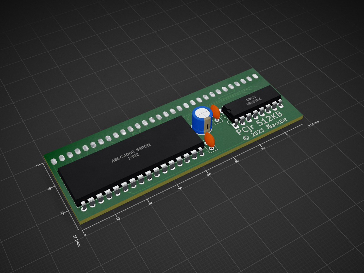
IBM PCjr (512KB sidecar expansion)

- Details: Adds 512KB, expanding total system memory to 640KB (if you already have 128KB internally).
- BOM: 1x THT AS6C4008-55PCN/PIN, 2x THT 0.1uF ceramic capacitors, 1x THT 10uF electrolytic capacitor, 1x THT 74LS151 logic chip, 2x30P 2.54mm female header.
- Installation: Plug sidecar into side of machine.
Korg 01/W LCD Fix

- Details: Adapter to fix the contrast when replacing the Korg 01/W LCD with a modern LED replacement
Plaster 64 (PLA replacement for Commodore 64)

- Details: Replaces MOS 906114 with exact
equations used in original device
- CAS delay: Improves compatibility on some systems.
- KERNAL Mode: Switch allows BackBit cartridge (any maybe others) to replace KERNAL ROM.
- Private Eyes Mode: Switch sets bus high to facilitate in-circuit testing.
- BOM: SMT ATF1502ASL-25AU44, 3x 2.54mm DIP switch, 28x header pins, optional 28P socket, and parts assembled on bottom of PCB listed in parts folder.
- Instructions: PCB requires SMT assembly.
- Installation: Program CPLD w/ ATDH1150USB programmer.
PLAster 128 (PLA replacement for Commodore 128)

- Details: Replaces MOS 8721 with exact equations used in original device
- Compatibility Mode: Switch allows cartridges to work in FAST mode.
- KERNAL Mode: Switch allows BackBit cartridge (any maybe others) to replace KERNAL ROM.
- Private Eyes Mode: Switch sets bus high to facilitate in-circuit testing.
- BOM: XC9572XL-*VQG64C, 3x 2.54mm DIP switch, 48x header pins, optional 48P socket, and parts assembled on bottom of PCB listed in parts folder.
- Instructions: PCB requires SMT assembly.
- Note: There is very limited height inside the C128 and you may want to modify this design to use Flip Pins (http://oshchip.org/products/Flip-Pins_Product)
- Some research credited to: https://c128.se/posts/silicon-adventures/
Tandy Color Computer 3 (512KB internal upgrade)

- Details: Expands base model's 128KB to 512KB. Timing window is very narrow. RC delay accomodates SRAM to work in place of DRAM.
- BOM: 1x SMT IS61C25616AS-25TLI, 1x SMT ATF1502ASL-25AU44, square header pins.
- Installation: Program CPLD w/ ATDH1150USB programmer. Remove existing RAM chips, plug memory board into expansion headers. Optionally remove ceramic caps C65 and C66.
- Note: I made a late change to the CUPL file to adjust the equations, which could fix some bus contention. I would recommend to test both the previous and current CUPL files to be certain.
Texas Instruments TI-99/4A (32KB sidecar expansion)

- Details: Fills in the system's memory map to get the maximum non-bankswitched RAM expansion. No pass-through port in this design. Need to add JTAG header if you don't have a programmer with a socket.
- BOM: 1x SMT CY62256NLL-70SNX (SOP-28), 1x SMT ATF1502ASL-25AU44, 5x SMT 0.1uF bypass capacitors, 44P 2.54mm edge connector.
- Installation: Program CPLD w/ ATDH1150USB programmer. Plug sidecar into side of machine.
- Case: https://www.printables.com/model/301498