

4 layers81.2 × 81.2 mm

 Eugene109/IRIS6
A PCB drone designed for swarm capabilities
ProPrj IRIS is an open-source printed circuit board by Eugene109, from the Eugene109/IRIS repository on GitHub, published under the GPL-3.0 licence. It is a 4-layer board of 92.7 × 72.5 mm with 259 parts on 179 nets, routed with 2,282 tracks and 601 vias.
Its parts include 83 capacitors, 82 resistors, 34 ICs, 24 transistors and 8 inductors. It belongs with the robots and motor control boards of this library.

A low-cost quadcopter platform designed for autonomous swarm operations.

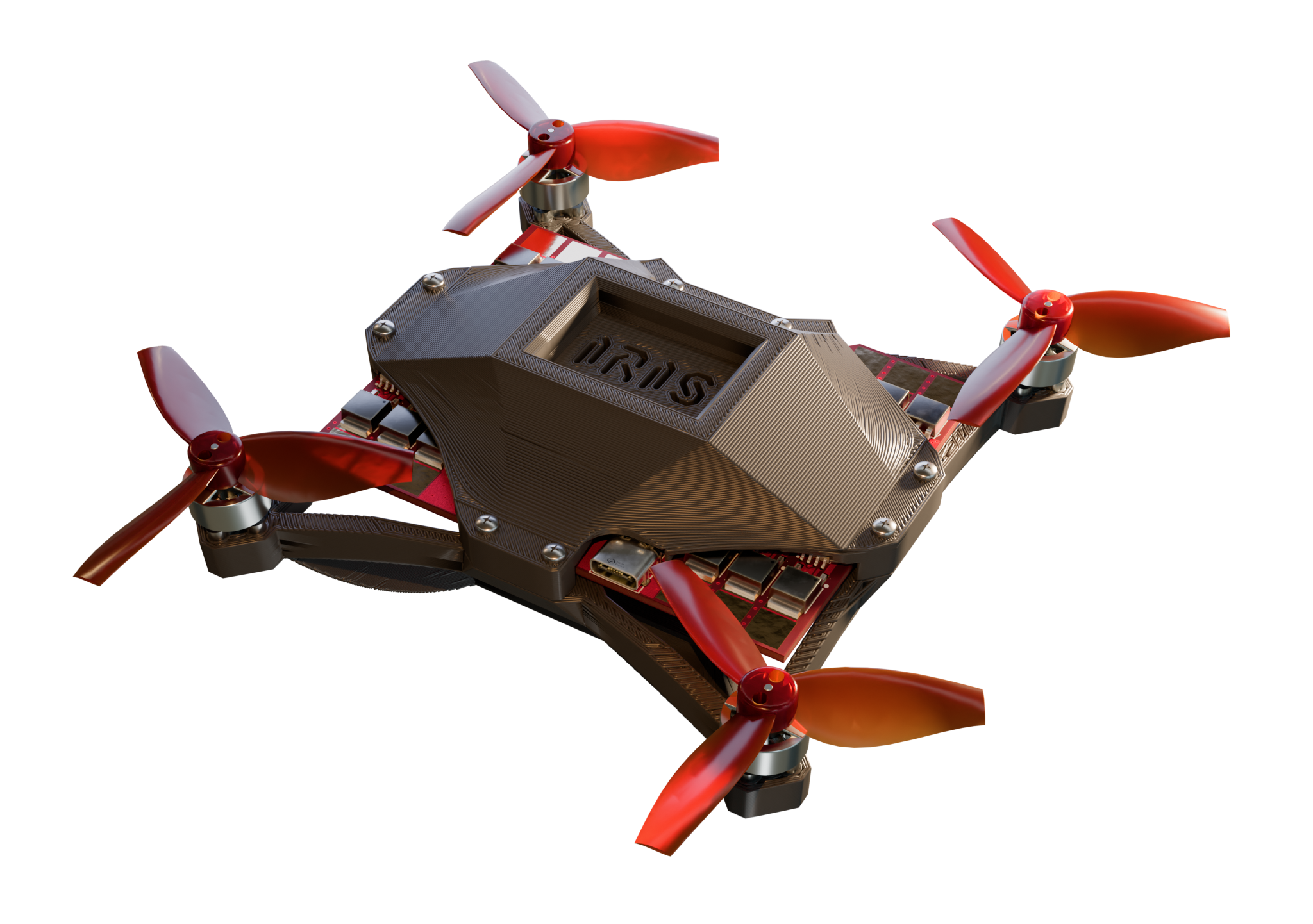
IRIS is centered around a mass-manufacturable low-cost PCB, containing a flight controller and 4 ESCs. Designed with the idea of delivering Skittles autonomously, IRIS is built from the ground-up for autonomous operation in swarms. With a rich sensor set and high degree of customizability, IRIS represents an accessible, low-cost entry into the world of autonomous and swarm drone operations. I began this project because I found a lack of accessible drone designs that are for more than just 'fun FPV flying', and I wanted to be able to program a drone to do cool things. IRIS represents a rethinking of small drone design, believing that small drones can and should be autonomous and that everyone should be able to program a drone.
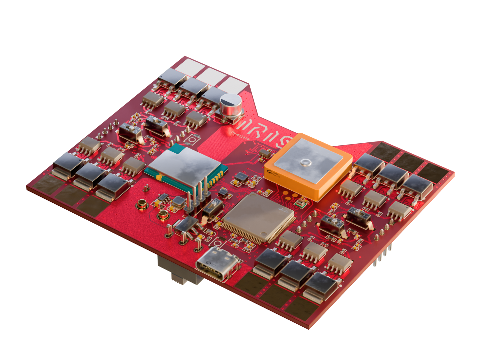
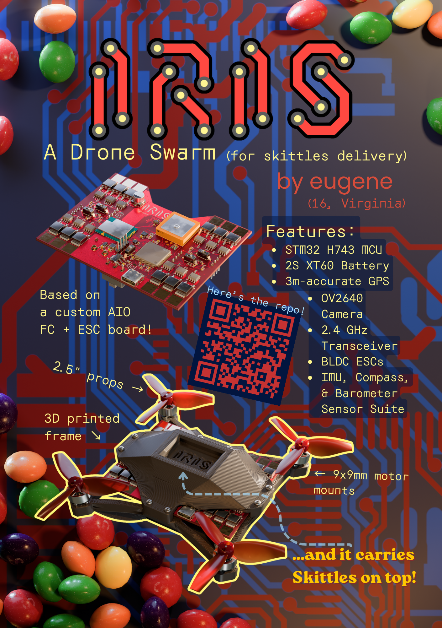
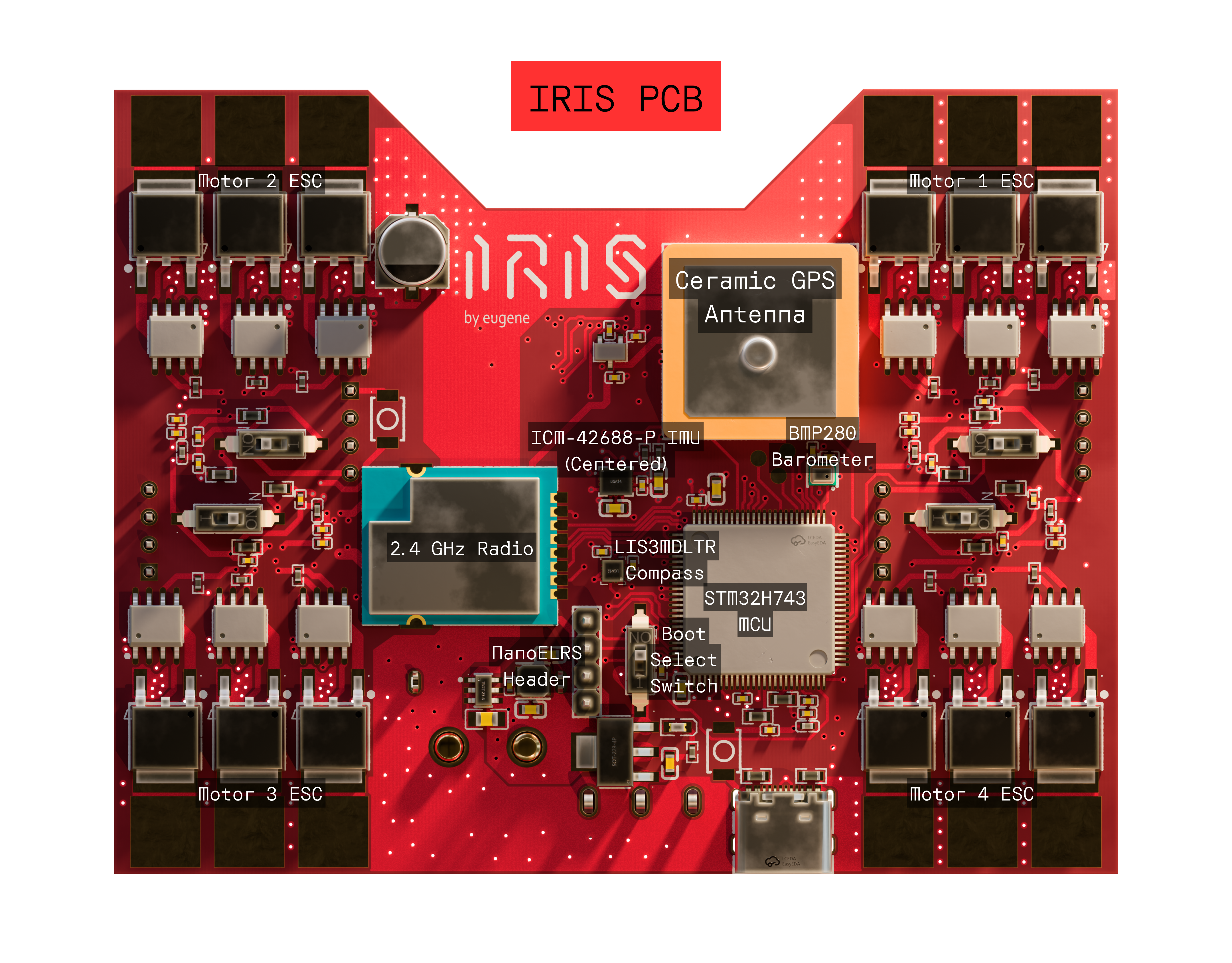
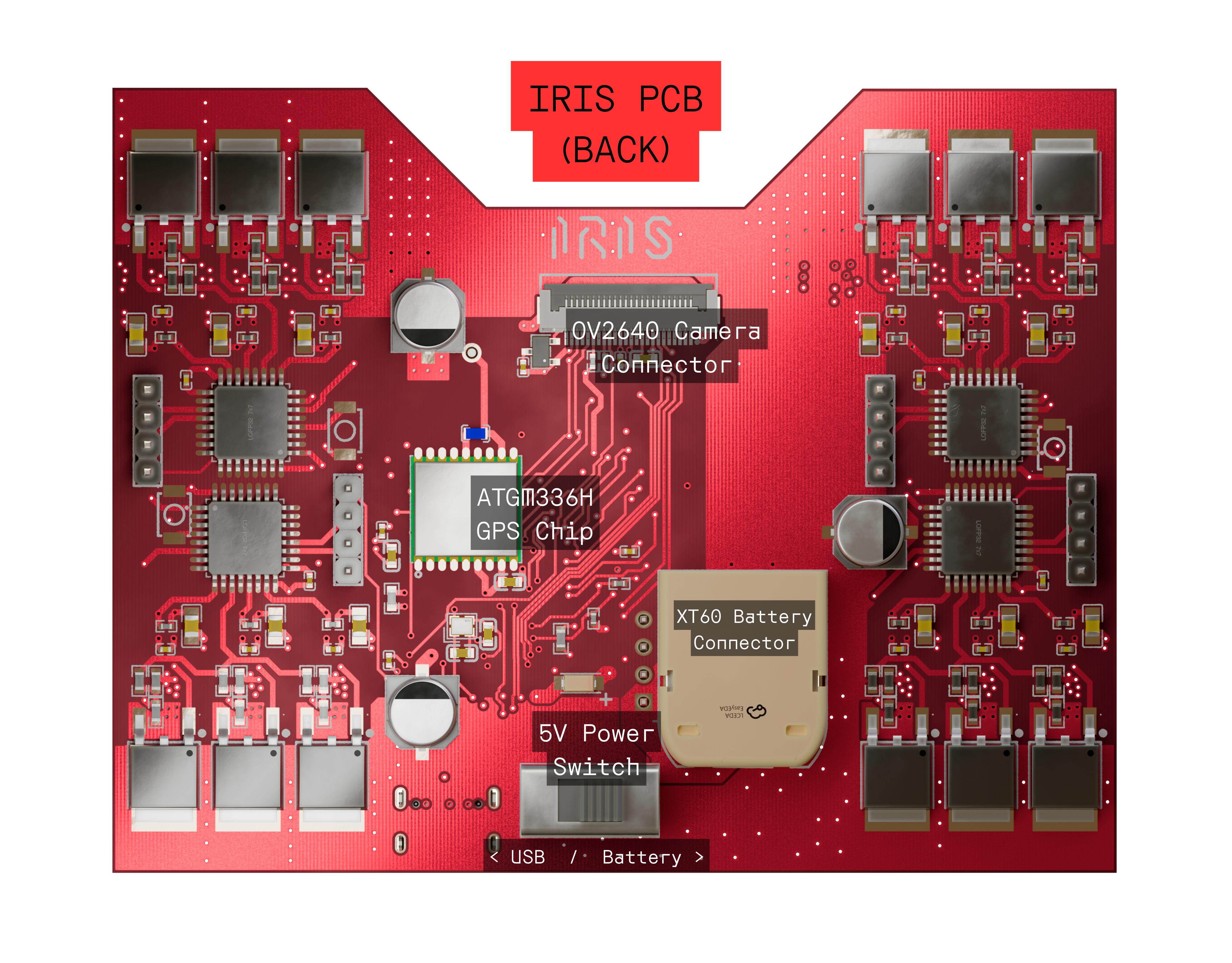
The PCB design features a 4-layer PCB stackup for lowered manufacturing costs, with a (nearly) continuous ground plane for reduced RF interference. The area under the MCU and core sensors also feature a continuous 3.3V power plane. The high voltage and current for the ESCs are routed on large copper pours on the bottom layer, with cross-layer connections connected by suture vias.
The total board dimensions are 3.650" by 2.856", a little larger than a credit card.
The main flight controller MCU is programmable over USB. The 4 ESC MCUs require a serial programmer, with ground, rx and tx exposed on header pins. All MCUs have a dedicated switch for a physical boot selector.
The ESC design features an STM32F303K8T6 microcontroller, a very powerful MCU that enables accurate back-emf drive even for high kV motors.
Loosely based off of this open-source design I found, https://electronoobs.com/eng_arduino_tut91.php, the wiring diagram was very helpful to guide the general layout of my ESC. The control logic is loosely based off of the arduino code, though it had to be completely rewritten to interface with STM32 hardware (really all BLDC motor control logic is the same, but nice understandable code was helpful).
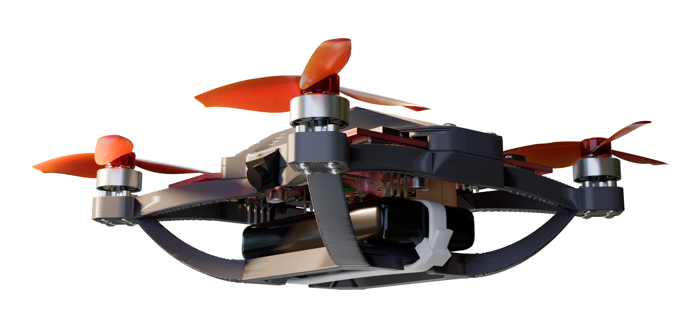
The frame design merges swooping curves and sharp geometric angles in a retrofuturistic visual style. Inspired by the Theme Building at LAX, the frame arms are each constructed with 3 catenary curves, with the bottom arches merging together to form the cradle for the battery.
The bottom also features a -30º camera mount, which facilitates autonomous navigation, and turns into the perfect FPV mount when flown inverted.
At the top of the frame, a little cradle with a minimalist IRIS logo debossed reserves space for a small collection of Skittles, easily dumped out by flipping the drone.
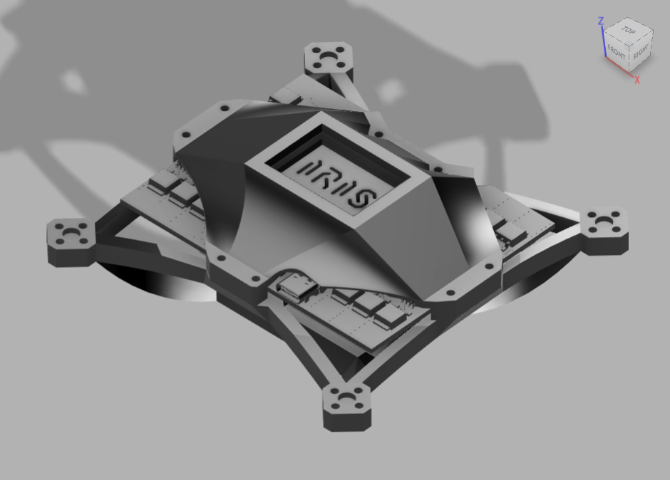
The drone frame is constructed in two pieces and held together by 8 M2 screws. The bottom half contains a battery mount and 4 9x9mm motor mounts, while the top half clamps the PCB down. The top cover shields the bulk of the PCB while leaving the high-current ESC MOSFET sections exposed for cooling, and is bolted down using 8 10mm long M2 screws and heat set inserts on the bottom half.
This project was made in the free software EasyEDA Pro, and the design is native to that software. The PCB design has been converted to a KiCAD project for easier access to the design, but there may be some errors that have occurred during the import process, in particular trace clearances and zone fill rules.
NOTE: The KiCAD imported project relies on 3D models and footprints from LCSC, which were imported using easyeda2kicad.py.
All of the files for the flight controller + ESC board are contained in pcb/, with fabrication files in pcb/fabrication/. All fabrication files are to JLCPCB specifications. All part numbers are from LCSC.
The frame CAD files can be found in the frame/ directory, with (metric) STL and 3MF exports ready for 3D printing. The cover and bottom were designed in the same Fusion360 Part, and the IRIS_Assembly.f3z is the total assembly including parts I did not design.
All of the renders on the documentation were created using Blender 5.1, and render files can be found in docs/render/.
Total cost from LCSC: $103.21 LCSC Quote
The PCB gerbers can be manufactured by JLCPCB with the simple 4-layer PCBA economical service. Two-sided automated assembly is quite expensive however, so first prototypes will be assembled manually using solder stencils. PCB components can be ordered from LCSC using the LCSC BOM.
NOTE: The large copper pours are connected directly to a lot of the pads, manual soldering will require the use of a hot air rework station and powerful soldering iron
Note: the full list of components for the PCB was not included in this BOM to save space, the component BOM can be found here
| Part | Description | Link | Price |
|---|---|---|---|
| FC+ESC | 4-layer PCB A Economic, HASL(leaded) finish, 2 stencils w/ framework | JLCPCB (Please upload ./pcb/fabrication/gerbers.zip to order the PCB) | 29.23 |
| FC+ESC | IRIS PCB Components | LCSC (Please upload ./pcb/fabrication/BOM_Board1_PCB1.xlsx to order the components) | 103.21 |
| Battery | 1000 mAh 2S LiPo with XT60 connector | Admiral | 9.99 |
| Motors | 4x 8000 kV 1103 Brushless DC | AliExpress | 23.99 |
| Propellers | Gemfan 2512 2.5Inch 3-Blade 1.5mm Hole Propeller - 4CW+4CCW | Pyrodrone | 4.99 |
| Camera | OV2640 with SCCB cable | AliExpress | 4.20 |
| Heat-set inserts | M2x2.5mm, 3.5mm OD Knurled Brass Threaded Heat Set Inserts | Rusty Bolt Shop | 1.70 |
| Frame screws | M2x10mm screws | The Rusty Bolt Shop | 2.02 |
| Motor mount screws | M2x8mm screws | The Rusty Bolt Shop | 2.56 |
| Vibration dampening foam | 3M Double Coated Urethane Foam Tape 4056 | Newegg | 14.99 |
Total: $196.88 (minus shipping)
This flight controller is capable of running Betaflight, and the configuration header for a Betaflight target can be found in firmware/betaflight/. The compiled binaries can be found in the same directory, and the .hex file is recommended. The source code can be found at the Betaflight firmware repository, and the config.h file can be copied into the config directory to build it yourself.
The flight control software can be flashed using the USB-C port on the aft of the drone. Simply plug it in and use STMCubeProgrammer to flash it!
The ESCs run custom firmware, named Zephyrus. The binaries and source code is available at its repository.
Zephyrus is currently capable of sensorless back-EMF drive, and runs on the STM32F303K8T6 MCU platform. The sensorless drive is powered by ADC zero-crossing detection synchronized with the PWM output to the MOSFET drivers. The choice to use software detection of zero-crossing over hardware comparators was for the increased flexibility as the firmware matures, enabling more interesting control systems than just zero-crossing alone.
The ESCs are a bit harder to flash, though they should require only a single flashing when the firmware is tuned. Connect a serial programmer (FTDI, hijack an Arduino, etc) to the RX, TX, and GND pins and flash the MCU using the ROM bootloader. To switch the MCU to the built-in bootloader to program, simply flip the boot selector switch and press the reset button.
Everything is GNU GPL-3.0
zephyrus firmware is licensed under MIT, check its repo for more information.
Trademark Notice: Skittles® is a registered trademark of Mars, Inc. This project is not affiliated with, or sponsored by Mars, Inc. References to Skittles and any associated imagery are for descriptive purposes only.
1103 BLDC motor 3D model used in Fusion Assembly is from GrabCAD by Dang Ngoc Duy
2.5" propeller 3D model used in Fusion Assembly is from GrabCAD by Buddhas_Priest
rostock_laage_airport_4k.exr is CC0 from PolyHaven, credit to Greg Zaal
Inspiration was taken from [Electronoobs's ESC design], informing the framework for a standard ESC architecture.
None of the PCB 3D models are my own work, they come from LCSC's libraries.
| Qty | Value | Footprint | References |
|---|---|---|---|
| 53 | ProPrj_IRI-easyedapro:C0402 | C2, C10, C11, C12, C13, C14, C15, C16, C105, C106, C107, C108, C109, C110, C114, C121 +37 | |
| 51 | ProPrj_IRI-easyedapro:R0603 | R1, R2, R3, R10, R15, R16, R17, R19, R20, R21, R22, R23, R24, R28, R29, R30 +35 | |
| 31 | ProPrj_IRI-easyedapro:R0402 | R11, R12, R13, R14, R18, R25, R26, R27, R31, R32, R37, R38, R39, R40, R50, R51 +15 | |
| 24 | ProPrj_IRI-easyedapro:TO-252-3_L6.6-W6.1-P4.57-LS9.9-BR-CW | Q1, Q2, Q10, Q11, Q12, Q13, Q14, Q15, Q16, Q17, Q18, Q19, Q20, Q21, Q22, Q23 +8 | |
| 13 | ProPrj_IRI-easyedapro:C0805 | C4, C5, C6, C36, C37, C38, C55, C57, C58, C59, C68, C70, C96 | |
| 12 | ProPrj_IRI-easyedapro:C0603 | C1, C25, C27, C94, C97, C98, C100, C103, C112, C113, C115, C116 | |
| 12 | ProPrj_IRI-easyedapro:SOIC-8_L4.9-W3.9-P1.27-LS6.0-BL | U1, U7, U10, U13, U14, U16, U17, U19, U20, U21, U22, U24 | |
| 5 | ProPrj_IRI-easyedapro:SW-SMD_2P-L6.2-W2.5-LS9.4 | U5, U6, U8, U12, U35 | |
| 5 | ProPrj_IRI-easyedapro:L0402 | L1, L2, L3, L4, L5 | |
| 5 | ProPrj_IRI-easyedapro:HDR-TH_4P-HX-PH254-01-04-Z-L11.5 | H1, H2, H3, H4, H5 | |
| 5 | ProPrj_IRI-easyedapro:SW-SMD_L3.9-W3.0-LS5.0 | SW1, SW2, SW3, SW4, SW5 | |
| 4 | ProPrj_IRI-easyedapro:CAP-SMD_BD6.3-L6.6-W6.6-LS7.2-FD_3 | C117, C118, C119, C120 | |
| 4 | ProPrj_IRI-easyedapro:LQFP-32_L7.0-W7.0-P0.80-LS9.0-BL | U9, U15, U18, U23 | |
| 1 | ProPrj_IRI-easyedapro:LGA-14_L3.0-W2.5-P0.50-TL | U2 | |
| 1 | Pad_e3517 | ||
| 1 | ProPrj_IRI-easyedapro:TSOT-23-6_L2.9-W1.6-P0.95-LS2.8-BL | U11 | |
| 1 | Pad_e836 | ||
| 1 | ProPrj_IRI-easyedapro:SOT-223-4_L6.5-W3.5-P2.30-LS7.0-BR | U25 | |
| 1 | Pad_e3373 | ||
| 1 | Pad_e2994 | ||
| 1 | Pad_e2995 | ||
| 1 | Pad_e2996 | ||
| 1 | ProPrj_IRI-easyedapro:LGA-12_L2.0-W2.0-P0.50-BL | U4 | |
| 1 | ProPrj_IRI-easyedapro:ANT-TH_L18.0-W18.0_C9900026472 | L8 | |
| 1 | ProPrj_IRI-easyedapro:LQFP-100_L14.0-W14.0-P0.50-LS16.0-BL | U33 | |
| 1 | Pad_e3376 | ||
| 1 | ProPrj_IRI-easyedapro:CRYSTAL-SMD_4P-L2.0-W1.6-BL | U31 | |
| 1 | Pad_e339 | ||
| 1 | Pad_e4442 | ||
| 1 | ProPrj_IRI-easyedapro:IND-SMD_L3.0-W3.0-1 | L6 | |
| 1 | Pad_e3516 | ||
| 1 | Pad_e4444 | ||
| 1 | ProPrj_IRI-easyedapro:LED0603-FD | U36 | |
| 1 | Pad_e680 | ||
| 1 | Pad_e4443 | ||
| 1 | ProPrj_IRI-easyedapro:SOT-23-3_L3.0-W1.6-P1.90-LS2.8-BR | U29 | |
| 1 | ProPrj_IRI-easyedapro:SW-TH_SHOU-HAN_SS12D10G4 | U34 | |
| 1 | Pad_e3514 | ||
| 1 | ProPrj_IRI-easyedapro:GPSM-SMD_ATGM336H-TR | U27 | |
| 1 | ProPrj_IRI-easyedapro:LGA-8_L2.5-W2.0-P0.65_AMP6127 | U3 | |
| 1 | ProPrj_IRI-easyedapro:SOT-23-3_L2.9-W1.6-P1.90-LS2.8-BR | U30 | |
| 1 | ProPrj_IRI-easyedapro:FPC-SMD_24P-P0.50_FPC-05F-24PH20 | FPC1 | |
| 1 | ProPrj_IRI-easyedapro:CONN-TH_XT60PW-M | CN1 | |
| 1 | Pad_e3380 | ||
| 1 | ProPrj_IRI-easyedapro:COMM-SMD_E01C-ML01SP4 | U32 | |
| 1 | ProPrj_IRI-easyedapro:IND-SMD_L1.8-W1.0 | L7 | |
| 1 | ProPrj_IRI-easyedapro:CAP-SMD_L3.2-W1.6-RD-C7171 | C99 | |
| 1 | ProPrj_IRI-easyedapro:USB-C-SMD_KH-TYPE-C-16P | USB3 |
It measures 92.7 × 72.5 mm and has 4 copper layers, 1.6 mm thick.
259 parts. The full list of its parts is on this page, with links to each part's symbol and footprint where PCBKit's library has them.
From the Eugene109/IRIS repository on GitHub, at the commit this page was made from: the board is pcb/kicad/ProPrj_IRIS.kicad_pcb and its schematic docs/logo/logo/logo.kicad_sch. PCBKit opens the board in the browser, with nothing to install.
Its repository publishes it under the GPL-3.0 licence: you may reuse it on that licence's terms (keep the author's notice, and for a copyleft licence share your changes alike).


m-labs/ionpak
A modern, low-cost universal controller for hot-cathode ionization vacuum gauges. (WIP)

proveskit/flight_controller_board
The main flight computer board for the PROVES Kit.


Sagit-chu/Flux60-HS
Open-source 60% Hall-effect keyboard PCB targeting 32 kHz scanning and native USB 8 kHz polling

Camperlux/vancontroller
VanController: ESP32-S3 12 V campervan controller board (6 fused relays, 6 PWM dimmers, CAN, RS485, GPS) - KiCad 10 design, manufacturing files and enclosure. Free for non-commercial use.

Mig-M27/Avionics-PCBs
Este repositório é usado para gerir as versões dos projetos KiCAD do sistema de Avionics da Porto Space Team. Está dividido em 2 secções: 1.