2 layers14.2 × 38.1 mm
 EthanKerman/STTS
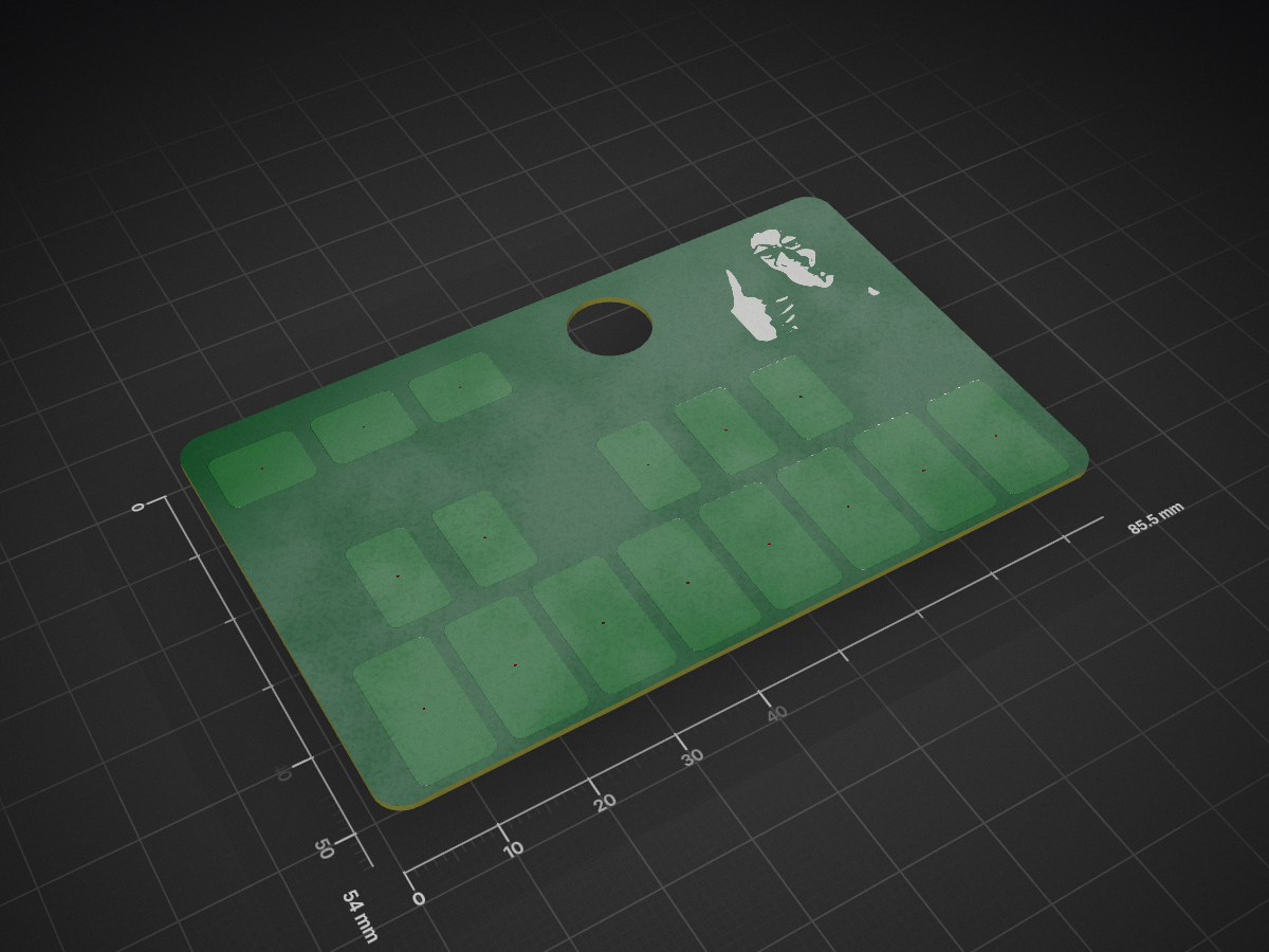
A behbeh credit card sized synth for your wallet. The keys are a full octave ad you can go up and down 2 more. The noise from a piezo disc which is why theres a hole in the board.
STTS is an open-source printed circuit board by EthanKerman, from the EthanKerman/STTS repository on GitHub. It is a 2-layer board of 85.5 × 54 mm with 43 parts on 25 nets, routed with 347 tracks and 16 vias.
It is built around the ATTINY1617-MN, B5819W and CR20160J. Its parts include 16 resistors, 2 capacitors, 1 IC and 1 diode. It belongs with the AVR (ATmega, ATtiny) boards of this library.


A behbeh credit card sized synth for your wallet. The keys are a full octave ad you can go up and down 2 more. The noise from a piezo disc which is why theres a hole in the board.
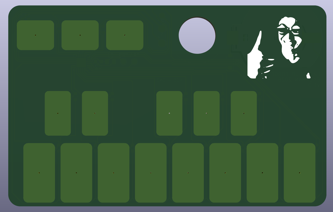
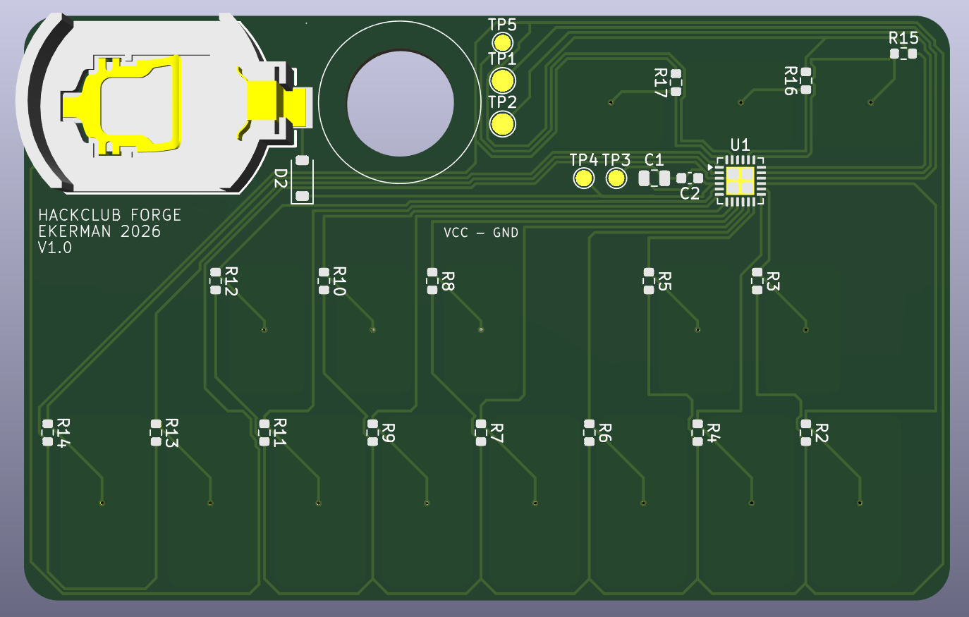
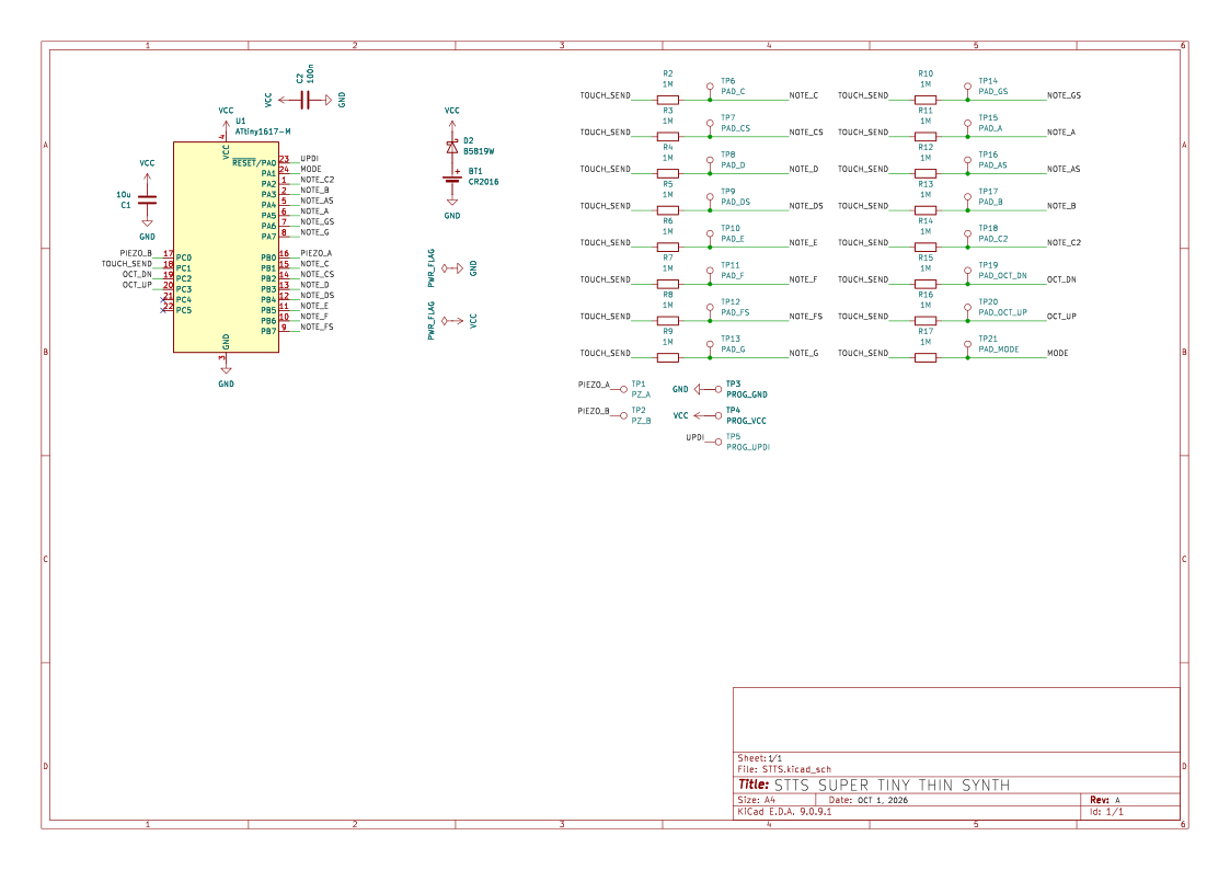
| Folder | Contents |
| hardware/ | KiCad 9 project (schematic, PCB, custom footprints in libs/) |
| firmware/STTS/ | Arduino sketch (megaTinyCore) |
| production/ | Gerbers, BOM, and placement (CPL) files for JLCPCB |
| images/ | Beautiful renders and screenshots |
Assembled by JLCPCB (Economic PCBA, bottom side), 5 boards.
Full BOM: bom.csv
Assembled by JLCPCB (Economic PCBA, bottom side), 5 boards.
Part Qty per board LCSC ATtiny1617-MNR 1 C614176 1 MΩ 0603 resistor 16 C22935 10 µF 0805 capacitor 1 C15850 100 nF 0603 capacitor 1 C14663 B5819W Schottky diode 1 C8598 CR2016 SMD holder 1 C964740 15 mm piezo disc (hand-soldered) 1 — Item Cost (USD) JLCPCB order (5 PCBs, assembly, components, shipping) $52.12 Piezo discs $5.00 3D-printed case (own printers) $0.00 Total $57.12
JLCPCB quote (5 assembled boards, 0.8 mm): $52.12
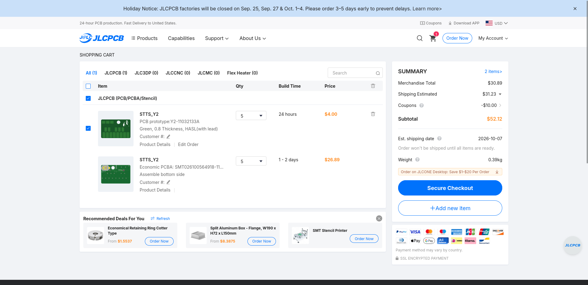
Piezo discs (bought separately): $5
Total: $57.12
Schematic yeye PCB layout (DRC clean) yeye Firmware v0.1 (compiles untested on hardware) yeye Front and back 3d printed covers yeye Boards ordered nono Bring up and touch tuning nono
A two-piece 3D-printed case: the bottom piece holds the card, and the top piece slides on after it's in. There's also a bottom-only version that works as a back cover. The piezo has a clear window so it can still vibrate, and the touch keys stay exposed.
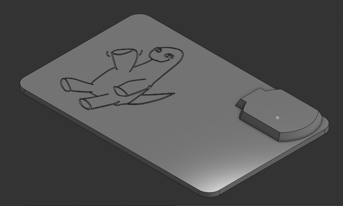
case/Designed by yours truly EthanKerman for Hack Club Forge
| Qty | Value | Footprint | References |
|---|---|---|---|
| 16 | 1M | Resistor_SMD:R_0603_1608Metric | R2, R3, R4, R5, R6, R7, R8, R9, R10, R11, R12, R13, R14, R15, R16, R17 |
| 1 | 100n | Capacitor_SMD:C_0603_1608Metric | C2 |
| 1 | 10u | Capacitor_SMD:C_0805_2012Metric | C1 |
| 1 | ATtiny1617-M | Package_DFN_QFN:QFN-24-1EP_4x4mm_P0.5mm_EP2.6x2.6mm | U1 |
| 1 | B5819W | Diode_SMD:D_SOD-123 | D2 |
| 1 | CR2016 | easyeda2kicad:BAT-SMD_BS-2016-B2AA001 | BT1 |
| 1 | LOGO | stts:brockgoofy1.3 | G*** |
| 1 | PAD_A | stts:TouchPad_White | TP15 |
| 1 | PAD_AS | stts:TouchPad_Black | TP16 |
| 1 | PAD_B | stts:TouchPad_White | TP17 |
| 1 | PAD_C | stts:TouchPad_White | TP6 |
| 1 | PAD_C2 | stts:TouchPad_White | TP18 |
| 1 | PAD_CS | stts:TouchPad_Black | TP7 |
| 1 | PAD_D | stts:TouchPad_White | TP8 |
| 1 | PAD_DS | stts:TouchPad_Black | TP9 |
| 1 | PAD_E | stts:TouchPad_White | TP10 |
| 1 | PAD_F | stts:TouchPad_White | TP11 |
| 1 | PAD_FS | stts:TouchPad_Black | TP12 |
| 1 | PAD_G | stts:TouchPad_White | TP13 |
| 1 | PAD_GS | stts:TouchPad_Black | TP14 |
| 1 | PAD_MODE | stts:TouchPad_Func | TP21 |
| 1 | PAD_OCT_DN | stts:TouchPad_Func | TP19 |
| 1 | PAD_OCT_UP | stts:TouchPad_Func | TP20 |
| 1 | PROG_GND | TestPoint:TestPoint_Pad_D1.5mm | TP3 |
| 1 | PROG_UPDI | TestPoint:TestPoint_Pad_D1.5mm | TP5 |
| 1 | PROG_VCC | TestPoint:TestPoint_Pad_D1.5mm | TP4 |
| 1 | PZ_A | TestPoint:TestPoint_Pad_D2.0mm | TP1 |
| 1 | PZ_B | TestPoint:TestPoint_Pad_D2.0mm | TP2 |
It measures 85.5 × 54 mm and has 2 copper layers, 0.8 mm thick.
43 parts, built around the ATTINY1617-MN, B5819W and CR20160J. The full list of its parts is on this page, with links to each part's symbol and footprint where PCBKit's library has them.
From the EthanKerman/STTS repository on GitHub, at the commit this page was made from: the board is hardware/STTS.kicad_pcb and its schematic hardware/STTS.kicad_sch. PCBKit opens the board in the browser, with nothing to install.
Its repository states no licence, so its author keeps all rights: ask EthanKerman before reusing the design.


e-tinkers/tinyAVR-Business-Card
This is the PCB design files for Hackaday 2024 Business Card Challenge contest

pdo/rc48-512
A 512KB RAM Card for the HP48GX Calculator ==========================================

coco-chameleon/chameleon-hardware
TRS-80 Color Computer cartridge emulator

owahltinez/coaster
Very simple battery-operated device. When you push a button, the light turns on for a few seconds and then it turns off.

RaniSargees/pcb-businesscard
a thin circuit board businesscard with a charlieplexed LED matrix display
