
4 layers99.5 × 64.8 mm
Muzy-4
regymm/muzy
2-layer and 4-layer FPGA development board with ZYNQ 7010/7020 400-pin BGA.
167 parts30GPL-3.0

An attempt at using large SDRAM ICs with the Raspberry Pi Pico
Sdram is an open-source printed circuit board by ethanjamesauto, from the ethanjamesauto/pico-sdram repository on GitHub. It is a 2-layer board of 25 × 55 mm with 10 parts on 63 nets, routed with 438 tracks and 34 vias.
It is built around the 74HC595 and MT48LC16M16A2P-6A:G. Its parts include 5 ICs and 4 capacitors. It belongs with the RP2040 boards of this library.


This project attempts to interface a Raspberry Pi Pico with a 32MB SDRAM IC.
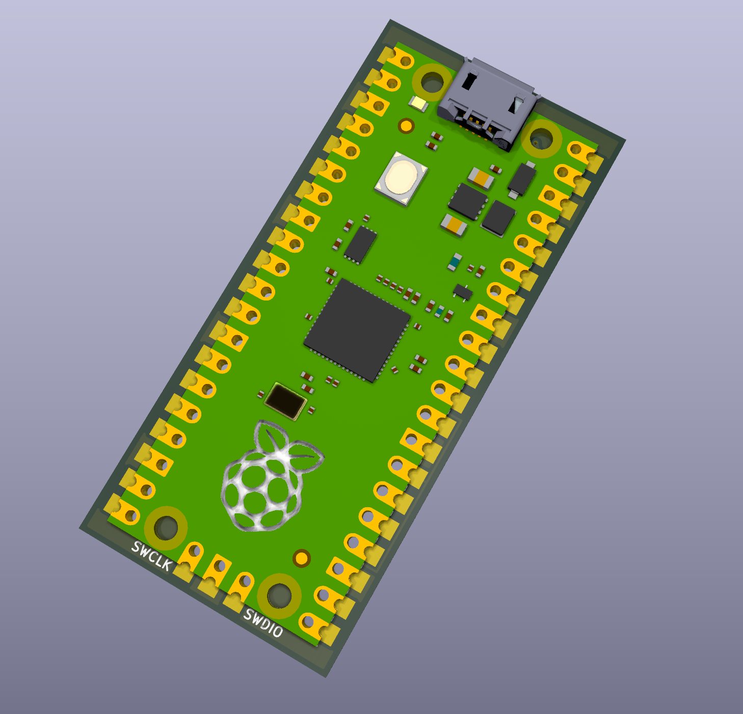
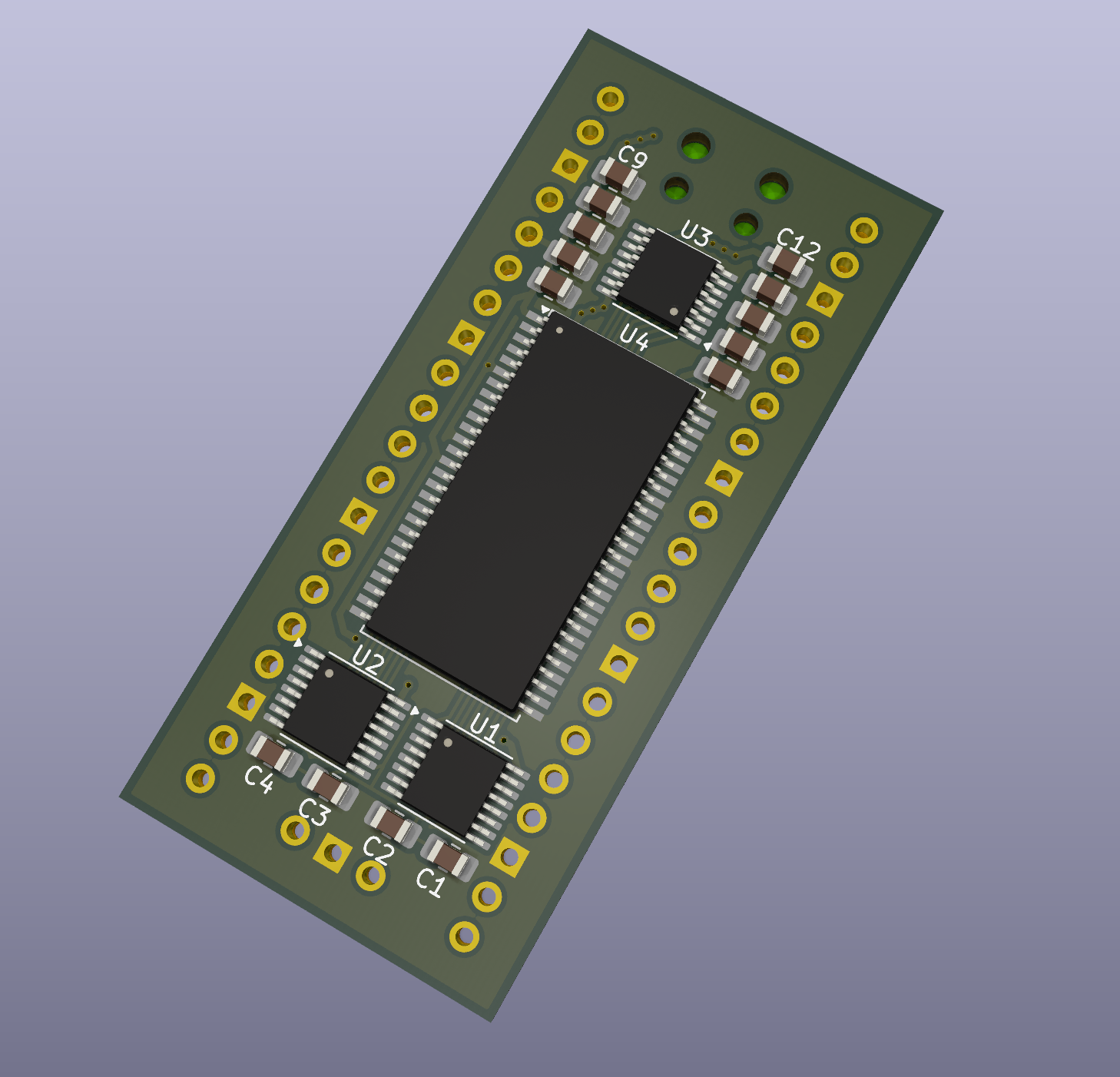
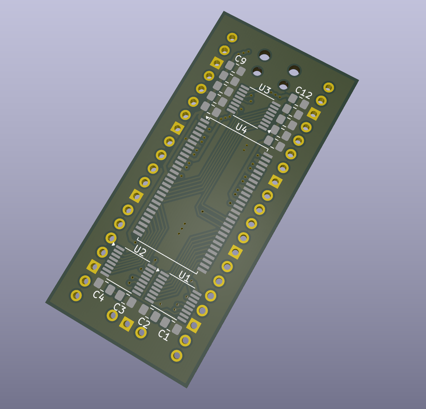
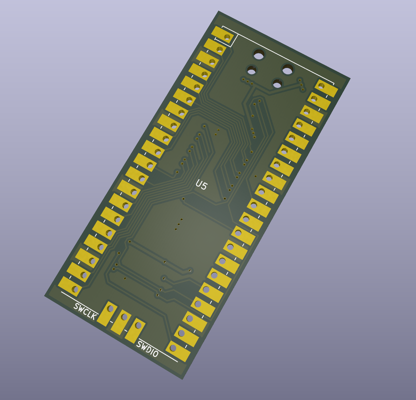
I have been able to successfully perform single and burst read/writes to the W9825G6KH SDRAM IC. I am running the SDRAM at half the speed of the rp2040 clock - the PIO state machines are running at the minimum clock divider value. I don't have full documentation, but some is available in:
SDRAM ICs are commonly available in sizes of up to 256MBit (32MB), and most have either an 8-bit or 16-bit data bus width. The control interface uses a total of 23 pins, so there are simply too many pins for an RP2040 to directly drive using GPIOs.
Shift registers may be reduce the number of GPIOs needed to interface with the ram. Because the RP2040 can only drive shift registers so quickly, the SDRAM chip would need to be driven at a lower clock speed. I propose a solution in which the control pins are driven using shift registers while the data bus is connected directly to the RP2040's GPIOs. This reduces the speed at which commands can be sent to the SDRAM, while still allowing the data bus to run at full speed. This solution has a drawback - it takes more time to send the two commands needed to initiate a read (row activate and read). However, this issue becomes neglible when most reads and writes use large block sizes (for example, when performing 1KB block reads and writes).
Eventually, I'd like to use this SDRAM interface with a PIO-based QSPI interface. The QSPI interface may then appear as a QSPI PSRAM and can be connected to the rp2350's QSPI bus. The pico can then translate "psram" accesses to sdram accesses, which would allow the pico to natively access sdram in the address space. This might not be possible.
// rgData: input, raw digital data array
// rgValue: output, decoded data array
// rgFlag: output, decoded flag array

c = rgData.length

for(var i = 0; i < c; i++){
   // take 4 least significant bits
   rgValue[i] = rgData[i] & 0xFF;
   // set flag other than zero for valid data
   rgFlag[i] = 1;
}

// value: value sample
// flag: flag sample
function Value2Text(flag, value) {
  var lower = value & 0xf;
  var addr10 = ((value >> 7) & 1) > 0;
  if (lower & 1) return "";
  if (lower == 14) return "NOP";
  if (lower == 6) return "BURST_TERM";
  if (lower == 10) return addr10 ? "READ_PRECHARGE" : "READ";
  if (lower == 2) return addr10 ? "WRITE_PRECHARGE" : "WRITE";
if (lower == 12) return "ACTIVATE";| Qty | Value | Footprint | References |
|---|---|---|---|
| 3 | 74HC595 | Package_SO:SOIC-16_3.9x9.9mm_P1.27mm | U1, U2, U3 |
| 2 | 100n | Capacitor_SMD:C_0805_2012Metric_Pad1.18x1.45mm_HandSolder | C2, C3 |
| 2 | 2.2u | Capacitor_SMD:C_0805_2012Metric_Pad1.18x1.45mm_HandSolder | C1, C4 |
| 1 | Jumper_2_Open | Jumper:SolderJumper-2_P1.3mm_Open_Pad1.0x1.5mm | JP1 |
| 1 | MT48LC16M16A2P | Package_SO:TSOP-II-54_22.2x10.16mm_P0.8mm | U4 |
| 1 | Pico | MCU_RaspberryPi_and_Boards:RPi_Pico_SMD_TH | U5 |
It measures 25 × 55 mm and has 2 copper layers, 1.6 mm thick.
10 parts, built around the 74HC595 and MT48LC16M16A2P-6A:G. The full list of its parts is on this page, with links to each part's symbol and footprint where PCBKit's library has them.
From the ethanjamesauto/pico-sdram repository on GitHub, at the commit this page was made from: the board is pcb/sdram-demo/sdram.kicad_pcb and its schematic pcb/sdram-demo/sdram.kicad_sch. PCBKit opens the board in the browser, with nothing to install.
Its repository states no licence, so its author keeps all rights: ask ethanjamesauto before reusing the design.
regymm/muzy
2-layer and 4-layer FPGA development board with ZYNQ 7010/7020 400-pin BGA.

Manawyrm/CMM2-JLC
Colour Maximite 2 - unofficial PCB design for automated assembly


vd-rd/sbc_at91sam9g10
Open hardware SBC module based on AT91SAM9G10 @266MHz with max 128MB RAM

vd-rd/sbc_at91sam9g20
Open hardware SBC module based on AT91SAM9G20 @400MHz with 128MB RAM

northernpaws/stm32h7-sdram-2layer
KiCad template for a TSOP-54 16M SDRAM routed to an LQFP-144 STM32H7 on two layers

OutBlade/s6la8
Open-source 8-channel logic analyzer: FX2LP + Spartan-6, with a sigrok driver. Design in progress, not yet built or tested.
