2 layers75 × 100 mm
Phased
Neumi/open_echo
Open Source echo sounder / depth sounder / SONAR for bathymetry and research. Arduino based and compatible.
77 parts530

 ethanhuang0117/Analog-Audio-Processing-Visualization-PCB-
8-band analog audio spectrum analyzer PCB with active filtering and 4-level LED visualization.
Audio Spectrum PCB is an open-source printed circuit board by ethanhuang0117, from the ethanhuang0117/Analog-Audio-Processing-Visualization-PCB- repository on GitHub. It is a 2-layer board of 135 × 150 mm with 216 parts on 141 nets, routed with 1,413 tracks and 0 vias.
It is built around the MCP6004-E/P, LM339 and CMA-4544PF-W. Its parts include 115 resistors, 45 capacitors, 40 diodes, 14 ICs and 1 connector. It belongs with the audio and music and sensors and measurement boards of this library.


A custom analog audio spectrum analyzer PCB that processes microphone audio across 8 frequency bands and displays signal intensity using 4-level LED indicators.
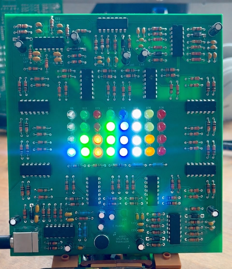
Download and Watch the PCB Demo
The system captures audio through an electret microphone, amplifies the signal, separates it into 8 frequency bands using active filters, and displays the signal intensity through LED indicators.
System Chain:
Microphone → Preamp → 8-Band Filters → Envelope Detection → Comparators → LED Visualization
| Band | Centre Frequency |
|---|---|
| 1 | 80 Hz |
| 2 | 160 Hz |
| 3 | 320 Hz |
| 4 | 640 Hz |
| 5 | 1.25 kHz |
| 6 | 2.5 kHz |
| 7 | 5 kHz |
| 8 | 10 kHz |
The initial design used passive filters, but were redesigned using cascaded Sallen-Key active filters to achieve greater roll-off and band separation.
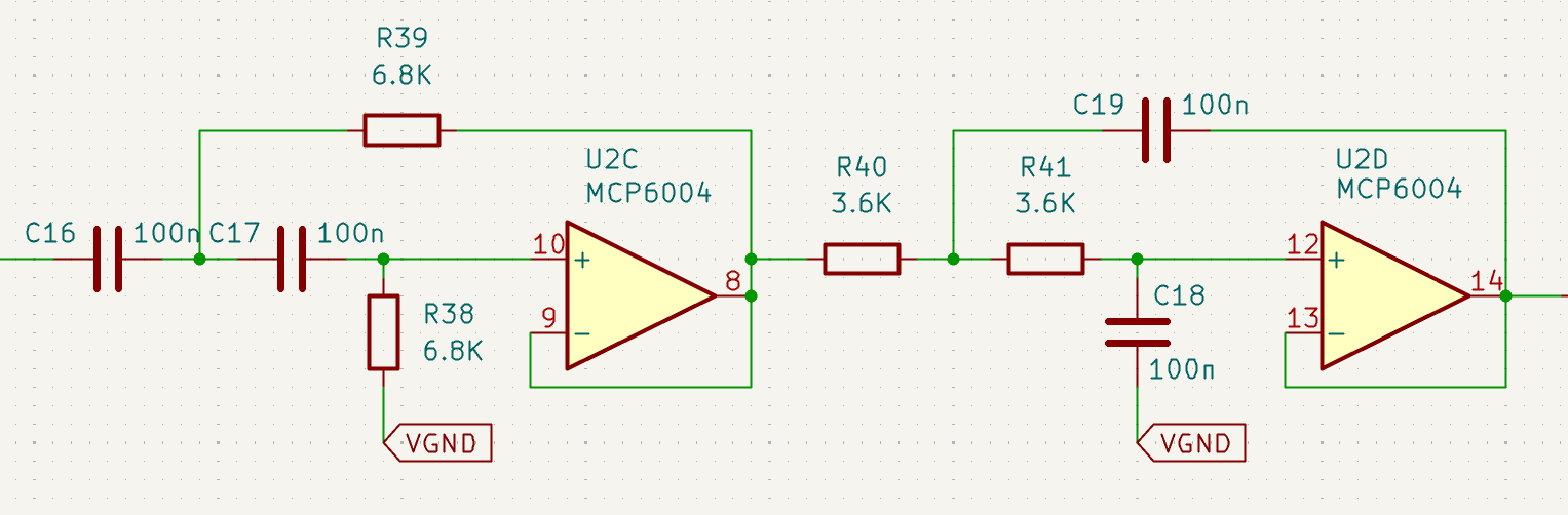
Each frequency band consists of a cascaded 2nd order Sallen-Key High Pass Filter (HPF) and Low Pass Filter (LPF).
Assumptions:
The cutoff frequencies are spaced by $\sqrt{2}$ from the centre frequency.
$$f_H = f_0 \times \sqrt{2}$$
$$f_L = \frac{f_0}{\sqrt{2}}$$
The general Sallen-Key cutoff frequency formula before simplification is:
$$f = \frac{1}{2\pi\sqrt{R_1 R_2 C_1 C_2}}$$
Applying the assumptions $R_1 = R_2 = R$ and $C_1 = C_2 = C$, this simplifies to:
$$f = \frac{1}{2\pi RC}$$
Rearranging for $R$:
$$R = \frac{1}{2\pi f C}$$
Step 1: Calculate HPF cutoff frequency
$$f_L = \frac{f_0}{\sqrt{2}} = \frac{640}{\sqrt{2}} = 453\text{Hz}$$
Step 2: Calculate LPF cutoff frequency
$$f_H = f_0 \times \sqrt{2} = 640 \times \sqrt{2} = 905\text{Hz}$$
Step 3: Calculate HPF resistor value ($C = 100\text{nF}$)
$$R_{HPF} = \frac{1}{2\pi \times 453 \times 100 \times 10^{-9}} = 3513\Omega \approx 3.6\text{k}\Omega$$
Step 4: Calculate LPF resistor value ($C = 100\text{nF}$)
$$R_{LPF} = \frac{1}{2\pi \times 905 \times 100 \times 10^{-9}} = 1759\Omega \approx 1.8\text{k}\Omega$$
| Band | Centre Frequency | C | HPF Cutoff | HPF R | LPF Cutoff | LPF R |
|---|---|---|---|---|---|---|
| 1 | 80Hz | 100nF | 56.6Hz | 27kΩ | 113Hz | 15kΩ |
| 2 | 160Hz | 100nF | 113Hz | 15kΩ | 226Hz | 6.8kΩ |
| 3 | 320Hz | 100nF | 226Hz | 6.8kΩ | 453Hz | 3.6kΩ |
| 4 | 640Hz | 100nF | 453Hz | 3.6kΩ | 905Hz | 1.8kΩ |
| 5 | 1.25kHz | 10nF | 884Hz | 18kΩ | 1.77kHz | 9.1kΩ |
| 6 | 2.5kHz | 10nF | 1.77kHz | 9.1kΩ | 3.54kHz | 4.7kΩ |
| 7 | 5kHz | 10nF | 3.54kHz | 4.7kΩ | 7.07kHz | 2.2kΩ |
| 8 | 10kHz | 10nF | 7.07kHz | 2.2kΩ | 14.1kHz | 1.1kΩ |
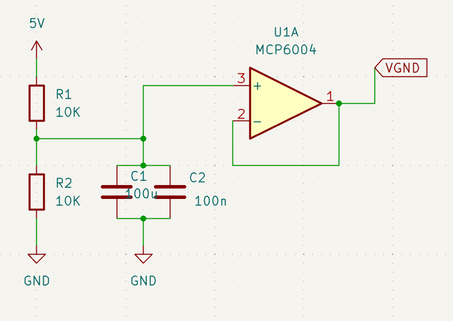
The circuit operates from a 5 V USB supply. Since audio signals oscillate about a center point, a virtual ground of 2.5V is used to allow the analog signal stages to operate from a single supply.
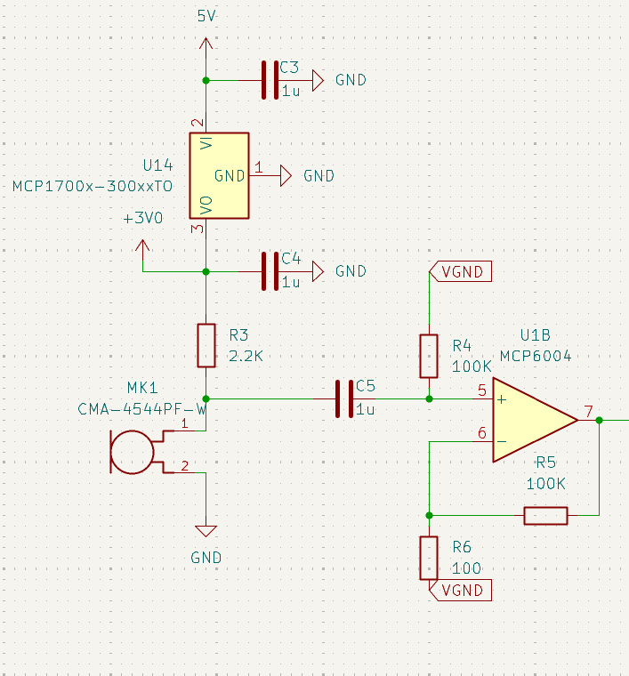
A CMA-4544PF-W electret microphone captures the incoming audio signal, which is amplified using an MCP6004 op-amp to provide a suitable signal level for the filter stages.
The CMA-4544PF-W was chosen because its frequency response of 20Hz-20kHz covers the full audio spectrum.
Each filtered signal passes through an envelope detector to convert the AC waveform into a varying DC voltage proportional to its amplitude.
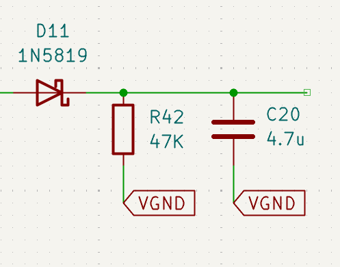
The RC time constant determines the decay time of the envelope:
$$\tau = R \times C = 47\text{k}\Omega \times 4.7\mu\text{F} = 221\text{ms}$$
This gives a smooth, natural decay that visually tracks the music without flickering too fast or responding too sluggishly.
Comparator circuits divide each detected signal into four amplitude thresholds. The resulting outputs drive four LEDs per frequency band to provide a 4-level visualization of audio intensity.
Individual circuit stages were first tested on breadboards and simulated in Multisim before PCB fabrication.
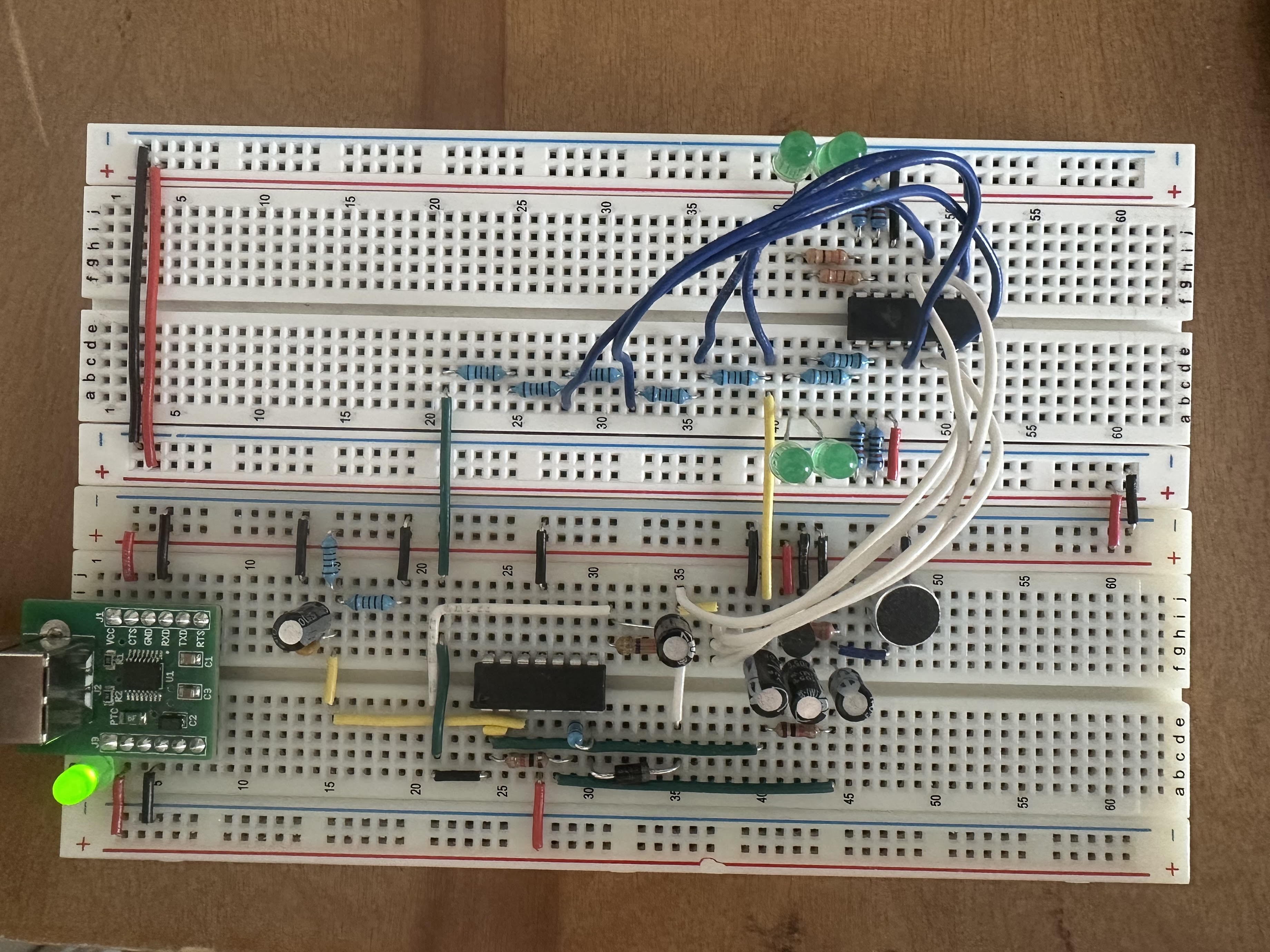
This iterative testing helped identify design issues before fabrication and reduced the need for PCB rework.
The validated circuit was translated into a custom PCB using KiCad, with component placement, routing, and ground pours optimized for a compact and reliable layout.
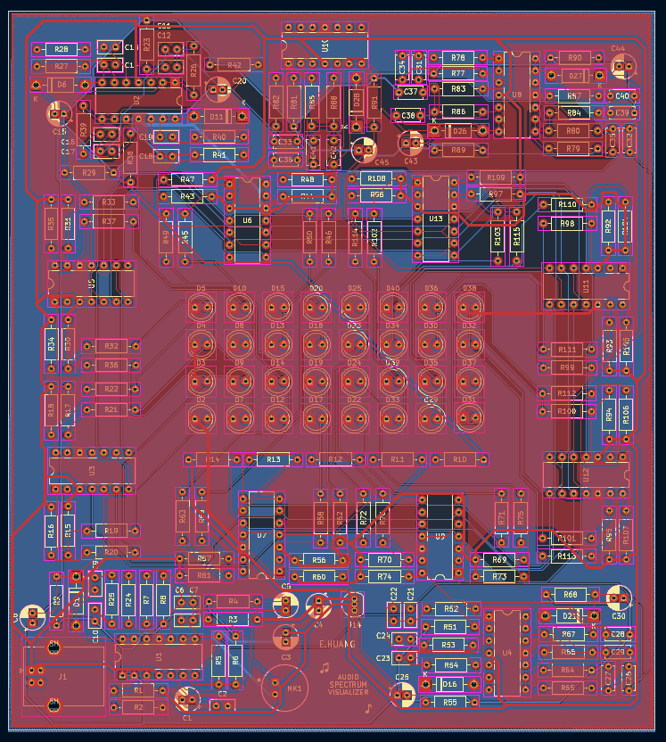
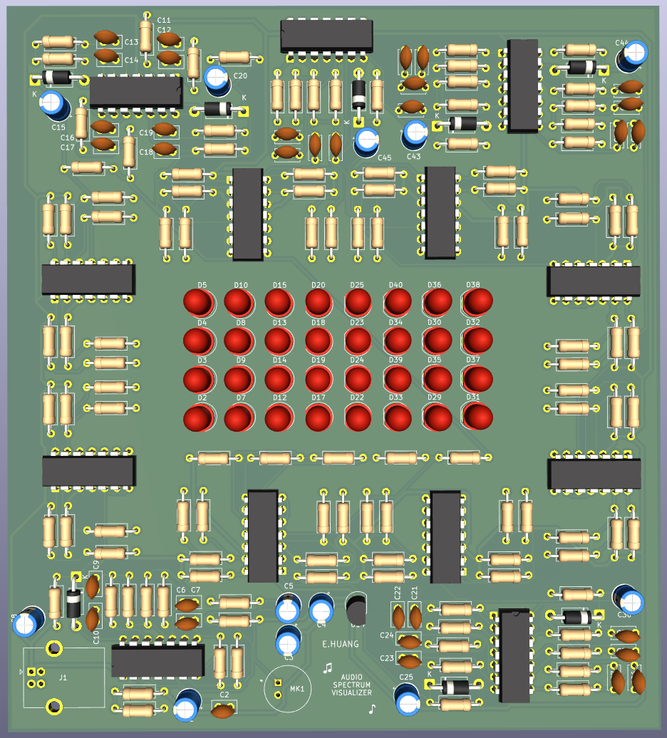
The completed PCB successfully processes audio through the 8 frequency bands and provides visual feedback through the LED array.
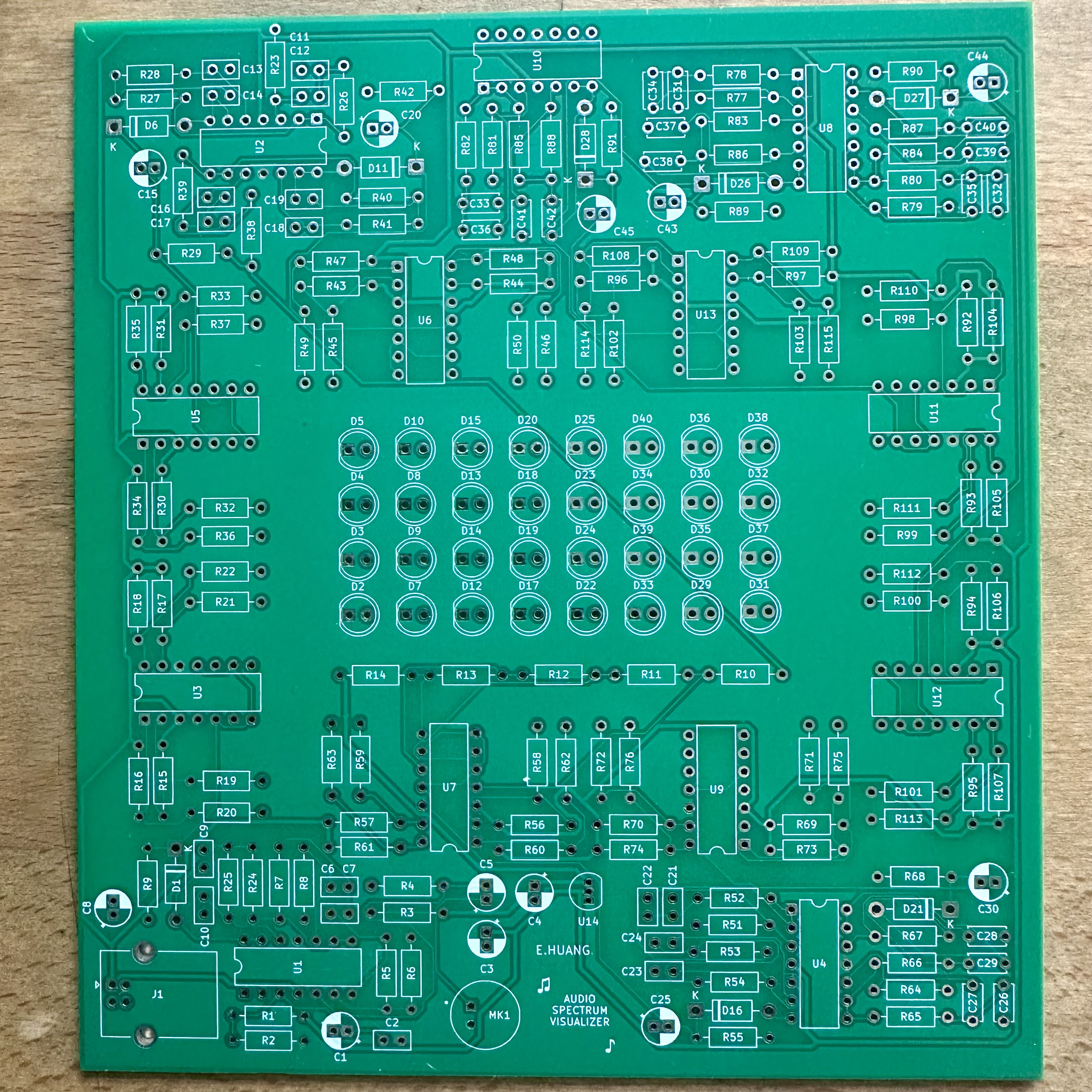
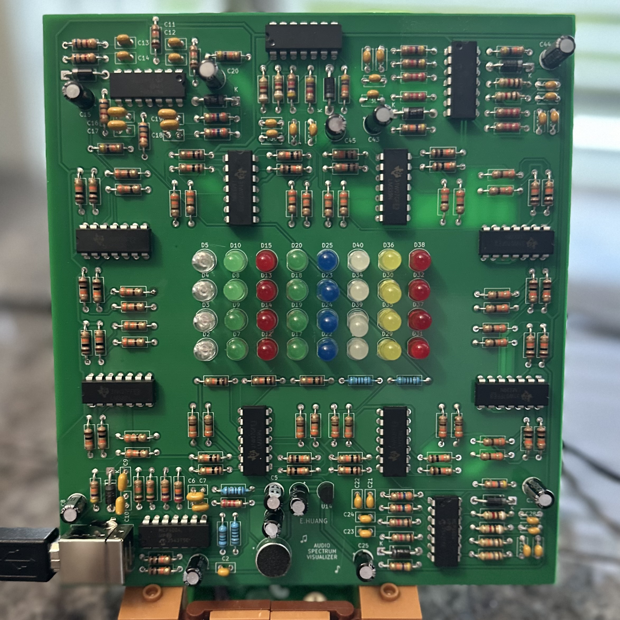
The original passive filter approach did not provide sufficient frequency separation. Sallen-Key active filters were implemented to improve roll-off and isolation between adjacent bands.
The preamplifier gain was iteratively adjusted during breadboard testing to provide sufficient signal amplitude without excessive amplification of noise.
Because the circuit operates from a 5 V USB supply, a virtual ground was implemented to allow the op-amp stages to process audio signals within the available supply range.
| Qty | Value | Footprint | References |
|---|---|---|---|
| 37 | 10K | Resistor_THT:R_Axial_DIN0207_L6.3mm_D2.5mm_P10.16mm_Horizontal | R1, R2, R12, R13, R14, R15, R16, R17, R18, R30, R104, R105, R106, R107, R108, R109 +21 |
| 32 | 330 | Resistor_THT:R_Axial_DIN0207_L6.3mm_D2.5mm_P10.16mm_Horizontal | R19, R20, R21, R22, R32, R33, R100, R101, R102, R103, R110, R111, R112, R113, R114, R115 +16 |
| 32 | LED | LED_THT:LED_D5.0mm | D2, D3, D10, D12, D13, D14, D15, D17, D18, D19, D20, D22, D23, D24, D25, D29 +16 |
| 17 | 100n | Capacitor_THT:C_Disc_D5.0mm_W2.5mm_P2.50mm | C2, C6, C7, C10, C11, C12, C13, C14, C16, C17, C18, C19, C21, C22, C23, C24 +1 |
| 16 | 10n | Capacitor_THT:C_Disc_D5.0mm_W2.5mm_P5.00mm | C26, C27, C28, C29, C31, C32, C33, C34, C35, C36, C37, C38, C39, C40, C41, C42 |
| 8 | 1N5819 | Diode_THT:D_DO-41_SOD81_P10.16mm_Horizontal | D1, D6, D11, D16, D21, D26, D27, D28 |
| 8 | 4.7u | Capacitor_THT:CP_Radial_D5.0mm_P2.00mm | C8, C15, C20, C25, C30, C43, C44, C45 |
| 8 | 47K | Resistor_THT:R_Axial_DIN0207_L6.3mm_D2.5mm_P10.16mm_Horizontal | R9, R29, R42, R55, R68, R89, R90, R91 |
| 8 | LM339 | Package_DIP:DIP-14_W7.62mm | U3, U5, U6, U7, U9, U11, U12, U13 |
| 5 | 2.2K | Resistor_THT:R_Axial_DIN0207_L6.3mm_D2.5mm_P10.16mm_Horizontal | R3, R79, R80, R83, R86 |
| 5 | MCP6004 | Package_DIP:DIP-14_W7.62mm | U1, U2, U4, U8, U10 |
| 4 | 15K | Resistor_THT:R_Axial_DIN0207_L6.3mm_D2.5mm_P10.16mm_Horizontal | R23, R24, R25, R26 |
| 4 | 3.6K | Resistor_THT:R_Axial_DIN0207_L6.3mm_D2.5mm_P10.16mm_Horizontal | R40, R41, R51, R52 |
| 4 | 4.7K | Resistor_THT:R_Axial_DIN0207_L6.3mm_D2.5mm_P10.16mm_Horizontal | R77, R78, R85, R88 |
| 4 | 6.8K | Resistor_THT:R_Axial_DIN0207_L6.3mm_D2.5mm_P10.16mm_Horizontal | R27, R28, R38, R39 |
| 4 | 9.1K | Resistor_THT:R_Axial_DIN0207_L6.3mm_D2.5mm_P10.16mm_Horizontal | R66, R67, R81, R82 |
| 3 | 1u | Capacitor_THT:CP_Radial_D5.0mm_P2.00mm | C3, C4, C5 |
| 2 | 1.1K | Resistor_THT:R_Axial_DIN0207_L6.3mm_D2.5mm_P10.16mm_Horizontal | R84, R87 |
| 2 | 1.8K | Resistor_THT:R_Axial_DIN0207_L6.3mm_D2.5mm_P10.16mm_Horizontal | R53, R54 |
| 2 | 100K | Resistor_THT:R_Axial_DIN0207_L6.3mm_D2.5mm_P10.16mm_Horizontal | R4, R5 |
| 2 | 18K | Resistor_THT:R_Axial_DIN0207_L6.3mm_D2.5mm_P10.16mm_Horizontal | R64, R65 |
| 2 | 27K | Resistor_THT:R_Axial_DIN0207_L6.3mm_D2.5mm_P10.16mm_Horizontal | R7, R8 |
| 2 | 5.1K | Resistor_THT:R_Axial_DIN0207_L6.3mm_D2.5mm_P10.16mm_Horizontal | R10, R11 |
| 1 | 100 | Resistor_THT:R_Axial_DIN0207_L6.3mm_D2.5mm_P10.16mm_Horizontal | R6 |
| 1 | 100u | Capacitor_THT:CP_Radial_D5.0mm_P2.00mm | C1 |
| 1 | CMA-4544PF-W | MyComponents:MIC_CMA-4544PF-W | MK1 |
| 1 | MCP1700x-300xxTO | Package_TO_SOT_THT:TO-92_Inline | U14 |
| 1 | USB_B | Connector_USB:USB_B_OST_USB-B1HSxx_Horizontal | J1 |
Neumi/open_echo
Open Source echo sounder / depth sounder / SONAR for bathymetry and research. Arduino based and compatible.

giant-axon/lu.i-neuron-pcb
Lu.i is an electronic neuron circuit mimicking and illustrating the basic dynamics of real, biological neurons. The printed circuit board (PCB) features a configurable, fully analog implementation of the leaky…

YYK2007/lif-neuron-pcb
Analog leaky-integrate-and-fire neuron PCB designed in KiCad.

BitDogLab/BitDogLab
Open-source educational hardware for embedded systems, programming, electronics, and physical computing.


aitesam961/OpenADSP
An Embedded Digital Signal Processing Device for Audio signals.

cruzsbrian/aurora
An addressable LED controller with graphical interface, audio input, and patterns programmed on an SD card.

GemsErasmusPlus/GEMS_Electronics
electronics design for the GEMS educational hardware
It measures 135 × 150 mm and has 2 copper layers, 1.6 mm thick.
216 parts, built around the MCP6004-E/P, LM339 and CMA-4544PF-W. The full list of its parts is on this page, with links to each part's symbol and footprint where PCBKit's library has them.
From the ethanhuang0117/Analog-Audio-Processing-Visualization-PCB- repository on GitHub, at the commit this page was made from: the board is Audio Spectrum PCB.kicad_pcb and its schematic Audio Spectrum PCB.kicad_sch. PCBKit opens the board in the browser, with nothing to install.
Its repository states no licence, so its author keeps all rights: ask ethanhuang0117 before reusing the design.