4 layers20.3 × 40 mm

 Eswar-426/ESP32-Industrial-Sensor-Controller1
A custom, compact PCB designed in KiCad 10 for an ESP32-based industrial temperature and humidity monitoring system.
ESP32-Industrial Sensor Controller is an open-source printed circuit board by Eswar-426, from the Eswar-426/ESP32-Industrial-Sensor-Controller repository on GitHub. It is a 2-layer board of 50.5 × 38.5 mm with 15 parts on 40 nets, routed with 183 tracks and 7 vias.
It is built around the ESP32-WROOM-32, AP2112K-3.3 and SHT31-DIS-F. Its parts include 5 capacitors, 4 resistors, 3 ICs, 2 switches and 1 connector. It belongs with the sensors and measurement boards and the ESP32 boards of this library.






A custom, compact PCB designed in KiCad 10 for an ESP32-based industrial temperature and humidity monitoring system.
The board integrates an ESP32-WROOM-32 Wi-Fi & Bluetooth microcontroller module, a high-precision Sensirion SHT31-DIS digital environmental sensor, and an ultra-low-dropout AP2112K-3.3 voltage regulator. It features dedicated I²C bus pull-up resistors, hardware Reset and Boot mode tactile switches, comprehensive decoupling networks, and an FTDI-compatible 6-pin UART interface for flashing and serial telemetry.
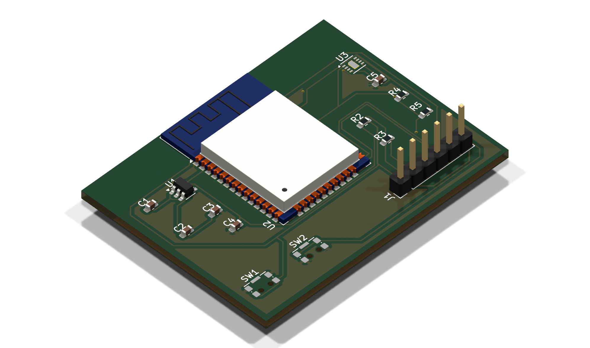
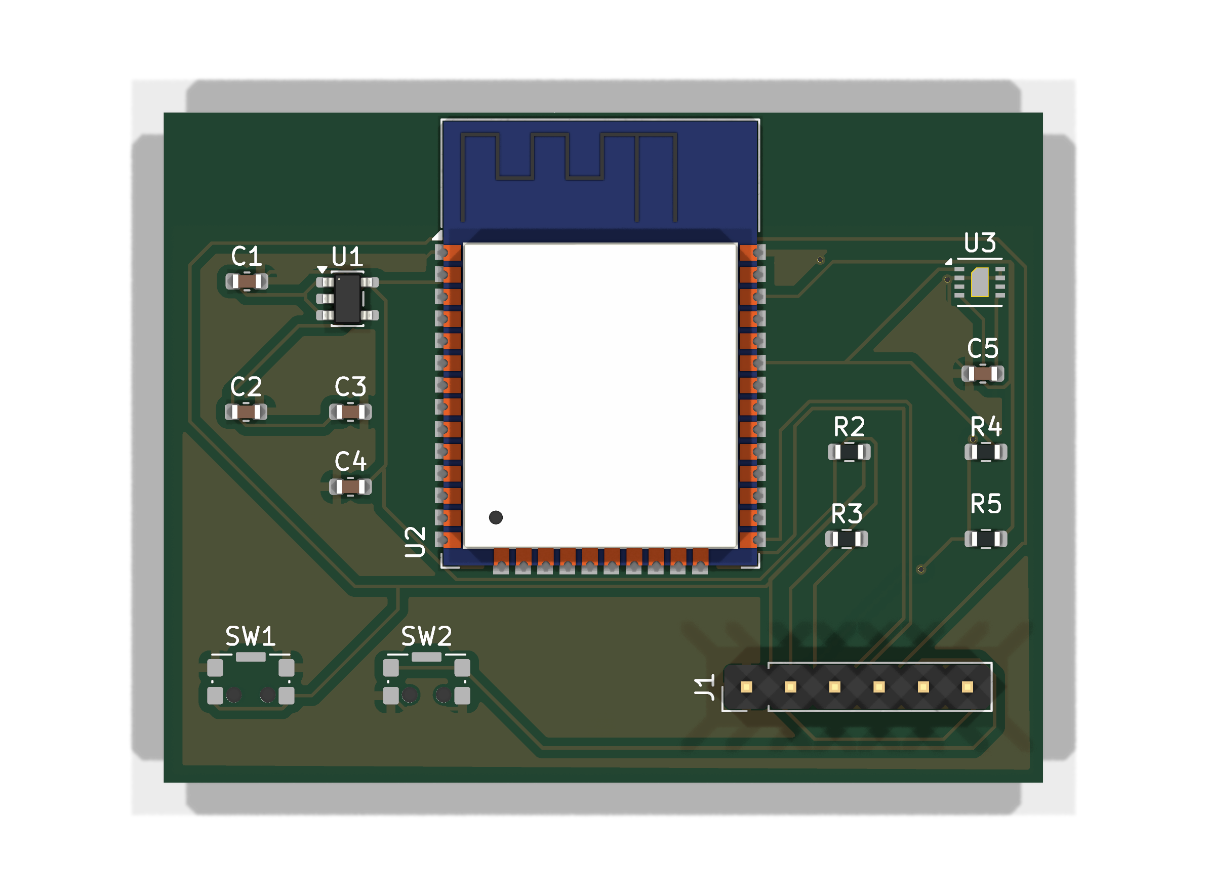
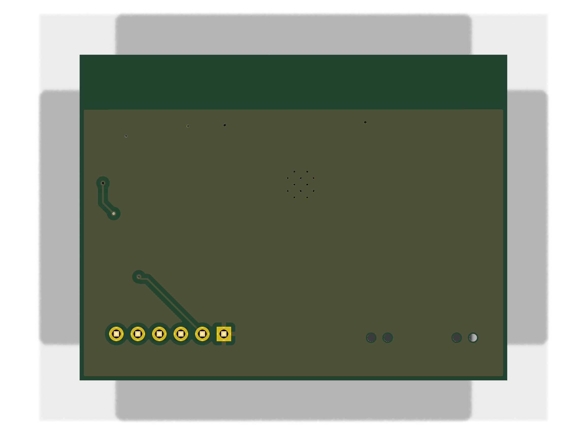
IO21 SDA, IO22 SCL) providing ±2% RH accuracy and ±0.2 °C temperature accuracy.TXD0/RXD0), power rails, reset line (EN), and boot line (IO0).SW1, EN to GND) and Boot Mode configuration (SW2, IO0 to GND) with external 10 kΩ pull-ups.
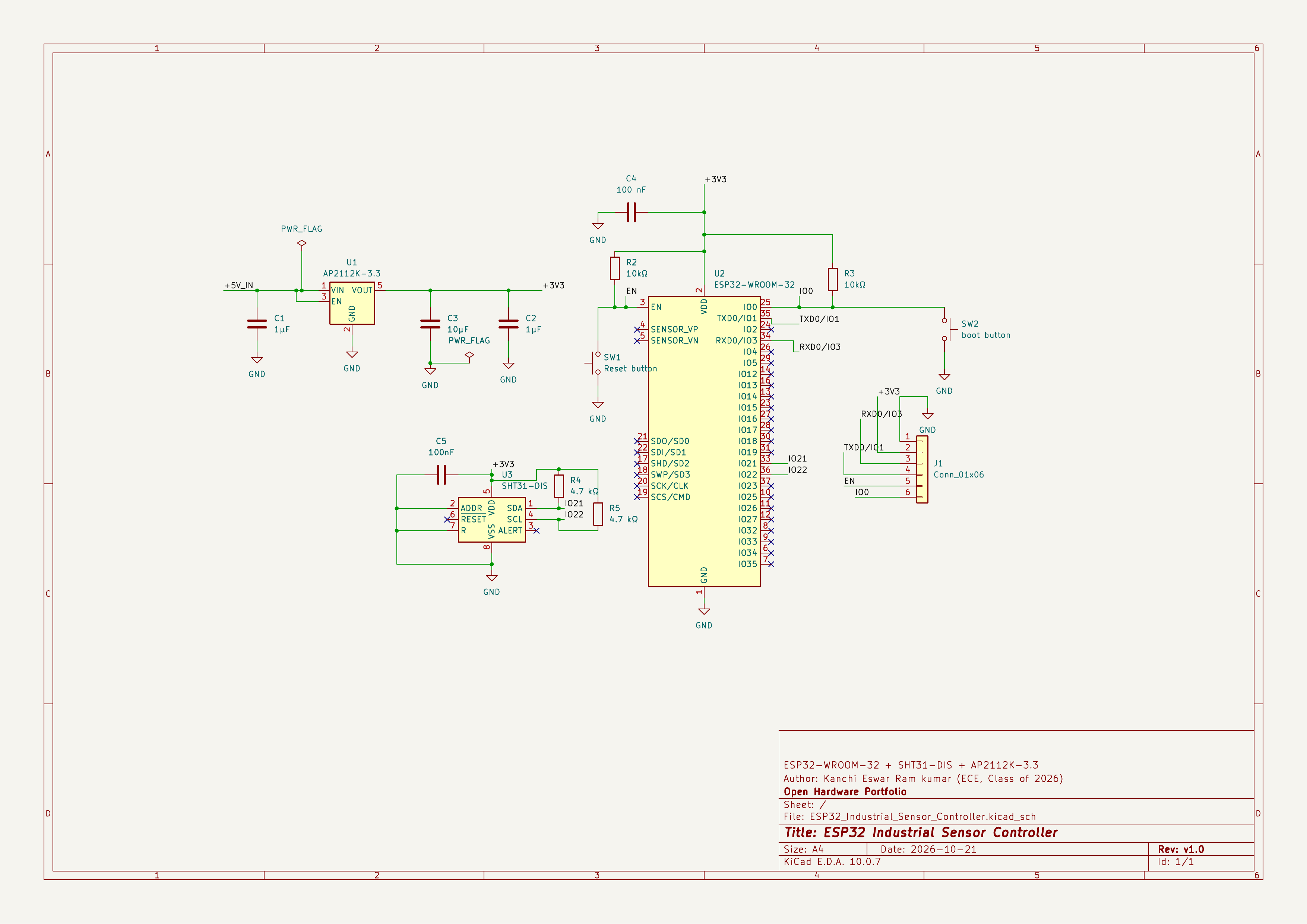
Complete schematic available in vector format: docs/schematic.pdf.
| Reference | Value / Part | Package / Footprint | Description | Qty |
|---|---|---|---|---|
| U1 | AP2112K-3.3 | SOT-23-5 | 600 mA Low-Dropout Linear Voltage Regulator (5V to 3.3V) | 1 |
| U2 | ESP32-WROOM-32 | SMD-38 (18×25.5 mm) | Espressif Dual-Core Wi-Fi & BLE Microcontroller Module | 1 |
| U3 | SHT31-DIS | DFN-8 (2.5×2.5 mm) | Sensirion High-Precision Digital Humidity & Temperature Sensor | 1 |
| C1, C2 | 1 µF | 0603 SMD | Input & Output Filter Capacitors for AP2112K LDO | 2 |
| C3 | 10 µF | 0603 SMD | Bulk Decoupling Capacitor for ESP32 3V3 Rail | 1 |
| C4, C5 | 100 nF | 0603 SMD | High-Frequency Bypass / Decoupling Capacitors (ESP32 & SHT31) | 2 |
| R2, R3 | 10 kΩ | 0603 SMD | Pull-Up Resistors for Boot (IO0) and Reset (EN) Lines | 2 |
| R4, R5 | 4.7 kΩ | 0603 SMD | Dedicated Pull-Up Resistors for I²C Bus (SDA, SCL) | 2 |
| SW1, SW2 | SPST Push Button | SMD (KMS2xxGP) | Reset (EN) and Boot (IO0) Control Switches | 2 |
| J1 | 6-Pin Header (1x06) | PinHeader 2.54 mm Vertical | UART Interface for Flashing, Debugging & Power Input | 1 |
Machine-readable CSV format: docs/bom.csv.
| Pin | Net Name | Target Device / Pin | Function / Usage |
|---|---|---|---|
| 1 | GND | System Ground Plane | Common ground connection |
| 2 | +3.3V | System 3.3 V Power Rail | 3.3 V supply rail / power monitor |
| 3 | RXD0 | ESP32 RXD0 (GPIO3) | Serial receive from external USB-UART programmer (TX) |
| 4 | TXD0 | ESP32 TXD0 (GPIO1) | Serial transmit to external USB-UART programmer (RX) |
| 5 | EN | ESP32 EN (Chip Enable) | Hardware reset control (active low) |
| 6 | IO0 | ESP32 GPIO0 (Boot) | Flashing bootloader entry (pull low during reset) |
| Sensor Pin | Net Name | ESP32 Pin | Function |
|---|---|---|---|
| Pin 1 (SDA) | IO21 | GPIO21 | I²C Serial Data (pulled up by R4: 4.7 kΩ to 3.3V) |
| Pin 4 (SCL) | IO22 | GPIO22 | I²C Serial Clock (pulled up by R5: 4.7 kΩ to 3.3V) |
Verification Scope Notice:
The hardware design has been fully verified using KiCad's Electrical Rules Check (ERC) and PCB Design Rules Check (DRC). Physical board fabrication, component assembly, firmware flashing, and hardware bench testing have not yet been performed. Fabrication constraints must be re-checked against specific manufacturer design capabilities (e.g., JLCPCB, PCBWay) prior to ordering production panels.
ESP32-Industrial-Sensor-Controller/
├── README.md                                      # Project overview, schematics, BOM, and pinout
├── .gitignore                                     # KiCad lock, backup, and local cache filters
├── hardware/
│   ├── ESP32_Industrial_Sensor_Controller.kicad_pro  # KiCad 10 project file
│   ├── ESP32_Industrial_Sensor_Controller.kicad_sch  # Complete schematic file
│   └── ESP32_Industrial_Sensor_Controller.kicad_pcb  # Fully routed PCB layout
└── docs/
    ├── schematic.pdf                              # Printable vector schematic
    ├── schematic.png                              # High-resolution schematic diagram
    ├── pcb-3d.png                                 # High-definition 3D raytraced board render
    ├── pcb-front.png                              # 3D top render
    ├── pcb-back.png                               # 3D bottom render
    ├── bom.csv                                    # Detailed Bill of Materials
    ├── drc-report.rpt                             # KiCad PCB DRC report (0 errors)
└── erc-report.rpt # KiCad Schematic ERC report (0 errors)PCB Design Completed — Prototype fabrication and hardware validation pending.
Kanchi Eswar Ram kumar (@Eswar-426)
ECE Undergraduate | Class of 2026
Developed as a PCB design and embedded systems portfolio project.
| Qty | Value | Footprint | References |
|---|---|---|---|
| 2 | 10kΩ | Resistor_SMD:R_0603_1608Metric | R2, R3 |
| 2 | 1µF | Capacitor_SMD:C_0603_1608Metric | C1, C2 |
| 2 | 4.7 kΩ | Resistor_SMD:R_0603_1608Metric | R4, R5 |
| 1 | 100 nF | Capacitor_SMD:C_0603_1608Metric | C4 |
| 1 | 100nF | Capacitor_SMD:C_0603_1608Metric | C5 |
| 1 | 10µF | Capacitor_SMD:C_0603_1608Metric | C3 |
| 1 | AP2112K-3.3 | Package_TO_SOT_SMD:SOT-23-5 | U1 |
| 1 | Conn_01x06 | Connector_PinHeader_2.54mm:PinHeader_1x06_P2.54mm_Vertical | J1 |
| 1 | ESP32-WROOM-32 | RF_Module:ESP32-WROOM-32 | U2 |
| 1 | Reset button | Button_Switch_SMD:SW_SPST_CK_KMS2xxGP | SW1 |
| 1 | SHT31-DIS | Sensor_Humidity:Sensirion_DFN-8-1EP_2.5x2.5mm_P0.5mm_EP1.1x1.7mm | U3 |
| 1 | boot button | Button_Switch_SMD:SW_SPST_CK_KMS2xxGP | SW2 |

Gecesars/01-plataforma-telemetria-broadcast
Plataforma Unificada de Telemetria de Estação Transmissora — baseline técnica e acompanhamento do projeto


kaushalch1/air-monitor
this is a portable air quality monitoring device designed to measure particulate matter and environmental conditions in real time.

IgorCulafic/PCBSmith
Open-source PCB design tools: KiCad workflows, automatic routing, design review and laser fabrication. Working toward plain-language circuit-to-board design.

jnicolson/panasonic_ac_wifi
Module to interface with the CN-CNT port on Panasonic airconditioner units


It measures 50.5 × 38.5 mm and has 2 copper layers, 1.6 mm thick.
15 parts, built around the ESP32-WROOM-32, AP2112K-3.3 and SHT31-DIS-F. The full list of its parts is on this page, with links to each part's symbol and footprint where PCBKit's library has them.
From the Eswar-426/ESP32-Industrial-Sensor-Controller repository on GitHub, at the commit this page was made from: the board is hardware/ESP32_Industrial_Sensor_Controller.kicad_pcb and its schematic hardware/ESP32_Industrial_Sensor_Controller.kicad_sch. PCBKit opens the board in the browser, with nothing to install.
Its repository states no licence, so its author keeps all rights: ask Eswar-426 before reusing the design.