2 layers63.7 × 105.5 mm
Spur demo without display
ericmutton/spur-project
Musings from my ECE undergraduate research project
104 parts4
 ericmutton/spur-project4
Musings from my ECE undergraduate research project
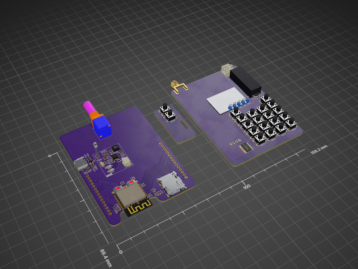
Spur demo card is an open-source printed circuit board by ericmutton, from the ericmutton/spur-project repository on GitHub. It is a 2-layer board of 158.2 × 89.4 mm with 150 parts on 136 nets, routed with 806 tracks and 82 vias.
It is built around the ESP32-C3-WROOM-02-H4, ISL91127IRNZ-T7A and PCF8575PWRE4, with the LM393, 103AT-2 and RK09711110EL among its other parts. Its parts include 40 resistors, 25 diodes, 22 capacitors, 20 switches and 7 ICs. It belongs with the radio and wireless boards and the ESP32 and RISC-V boards of this library.


Musings in preparation for the 2025 Summer Platform for Undergraduate Research.
This repository contains the project files created during my Fall 2024 and Spring 2025 semesters.
The EDA schematic captures and prototype PC boards are maintained in separate KiCAD projects in the Hardware directory.
The source code utilizing either the Espressif Systems ESP-IDF Arduino Core (using FreeRTOS) for experimentation or the Zephyr Standalone Application (using ZephyrRTOS) constituting the base radio platform firmware are both maintained in the Software directory.
The scope of this research project is to build a two-way radio communications platform that remains extensible in arbitrary 'all-mode' FM modulation in both firmware and hardware.
This means adopting modern real-time operating system ecosystems, particularly the two RTOS under consideration are:
For the hardware, the platform is to allow off-the-shelf (and few bespoke) integration of:
For the purposes of this project, the SA868 is limited to arbitrary FM modes:
In Analog FM Voice, a parrot test or signal strength report (Readability-Strength-Tone) would be satisfactory.
A first-principles approach in designing this platform is to be taken on:
After discovering a lack of ZephyrRTOS Charge API charge enable in the Cirrus Logic implementation of the ti,bq24190, this research project migrated to FreeRTOS. This migration allowed for the creation of bespoke 'device drivers' for the chips utilized in the radio platform. Print debugging was satisfactory in the making of the platform firmware and so the use of OpenOCD with ESP-Prog board was only researched. Zephyr abstractions listed in part 3 of approach were considered and not implemented after the migration to FreeRTOS.
The scope of this project during the one full academic semester resulted in a functional prototype of the radio platform on two breadboards capable of UHF operation of local Richardson city amateur radio infrastructure and two-way communications with a comparable handheld radio. Afterwards in the Spring 2025 semester a handheld radio form-factor two-layer PCB was designed under the Hardware/KiCAD/spur-demo directory.
This project now contains demonstrable embedded radio firmware and human-machine interface design efforts for handheld radio operation.
| Qty | Value | Footprint | References |
|---|---|---|---|
| 20 | D | Diode_SMD:D_0603_1608Metric | D1:1, D1:2, D1:3, D1:4, D1:5, D2:1, D2:2, D2:3, D2:4, D2:5, D3:1, D3:2, D3:3, D3:4, D3:5, D4:1 +4 |
| 17 | 10k | Resistor_SMD:R_0603_1608Metric | R1, R6, R11, R12, R15, R16, R17, R18, R19, R20, R21, R22, R23, R33, R34, R40 +1 |
| 9 | 10u | Capacitor_SMD:C_0603_1608Metric_Pad1.08x0.95mm_HandSolder | C2, C5, C6, C7, C8, C9, C14, C19, C22 |
| 5 | TestPoint | TestPoint:TestPoint_Loop_D2.54mm_Drill1.5mm_Beaded | TP1, TP2, TP3, TP4, TP5 |
| 4 | 1u | Capacitor_SMD:C_0603_1608Metric_Pad1.08x0.95mm_HandSolder | C1, C13, C20, C21 |
| 4 | LED | LED_SMD:LED_0603_1608Metric_Pad1.05x0.95mm_HandSolder | D3, D4, D5, D6 |
| 3 | 0.1u | Capacitor_SMD:C_0603_1608Metric_Pad1.08x0.95mm_HandSolder | C15, C16, C17 |
| 3 | 100k | Resistor_SMD:R_0603_1608Metric | R13, R30, R31 |
| 2 | 0k | Resistor_SMD:R_0603_1608Metric | R24, R25 |
| 2 | 1M | Resistor_SMD:R_0603_1608Metric | R9, R10 |
| 2 | 1x15 | Connector_PinHeader_2.54mm:PinHeader_1x15_P2.54mm_Vertical | J8, J9 |
| 2 | 2.2k | Resistor_SMD:R_0603_1608Metric | R38, R39 |
| 2 | 22u | Capacitor_SMD:C_0603_1608Metric_Pad1.08x0.95mm_HandSolder | C10, C11 |
| 2 | 680k | Resistor_SMD:R_0603_1608Metric | R29, R36 |
| 1 | # | Button_Switch_THT:SW_PUSH_6mm_H7.3mm | SW17 |
| 1 | * | Button_Switch_THT:SW_PUSH_6mm_H7.3mm | SW15 |
| 1 | 0 | Button_Switch_THT:SW_PUSH_6mm_H7.3mm | SW16 |
| 1 | 0R | Resistor_SMD:R_0603_1608Metric | R5 |
| 1 | 1 | Button_Switch_THT:SW_PUSH_6mm_H7.3mm | SW3 |
| 1 | 100k 5% | Resistor_SMD:R_0603_1608Metric | R28 |
| 1 | 103AT-2 | spur-demo:103AT2 | TH1 |
| 1 | 150k | Resistor_SMD:R_0603_1608Metric | R32 |
| 1 | 1N5819 | Diode_SMD:D_0603_1608Metric_Pad1.05x0.95mm_HandSolder | D2 |
| 1 | 1k | Resistor_SMD:R_0603_1608Metric | R35 |
| 1 | 1u | Inductor_SMD:L_Coilcraft_XxL4020 | L2 |
| 1 | 1uF | Capacitor_SMD:C_0603_1608Metric_Pad1.08x0.95mm_HandSolder | C3 |
| 1 | 2 | Button_Switch_THT:SW_PUSH_6mm_H7.3mm | SW4 |
| 1 | 2.27k | Resistor_SMD:R_0603_1608Metric | R3 |
| 1 | 2.2M | Resistor_SMD:R_0603_1608Metric | R8 |
| 1 | 2.2u | Inductor_SMD:L_Coilcraft_XxL4020 | L1 |
| 1 | 265R | Resistor_SMD:R_0603_1608Metric | R4 |
| 1 | 2k | Resistor_SMD:R_0603_1608Metric | R37 |
| 1 | 3 | Button_Switch_THT:SW_PUSH_6mm_H7.3mm | SW5 |
| 1 | 330k | Resistor_SMD:R_0603_1608Metric | R14 |
| 1 | 4 | Button_Switch_THT:SW_PUSH_6mm_H7.3mm | SW7 |
| 1 | 4.7u | Capacitor_SMD:C_0603_1608Metric_Pad1.08x0.95mm_HandSolder | C18 |
| 1 | 47n | Capacitor_SMD:C_0603_1608Metric_Pad1.08x0.95mm_HandSolder | C4 |
| 1 | 5 | Button_Switch_THT:SW_PUSH_6mm_H7.3mm | SW8 |
| 1 | 5.1K | Resistor_SMD:R_0603_1608Metric | R26 |
| 1 | 5.1k | Resistor_SMD:R_0603_1608Metric | R27 |
| 1 | 56p | Capacitor_SMD:C_0603_1608Metric_Pad1.08x0.95mm_HandSolder | C12 |
| 1 | 6 | Button_Switch_THT:SW_PUSH_6mm_H7.3mm | SW9 |
| 1 | 6.86k | Resistor_SMD:R_0603_1608Metric | R2 |
| 1 | 7 | Button_Switch_THT:SW_PUSH_6mm_H7.3mm | SW11 |
| 1 | 8 | Button_Switch_THT:SW_PUSH_6mm_H7.3mm | SW12 |
| 1 | 9 | Button_Switch_THT:SW_PUSH_6mm_H7.3mm | SW13 |
| 1 | BOOT | Button_Switch_SMD:SW_SPST_CK_RS282G05A3 | SW1 |
| 1 | BQ24193RGER | spur-demo:QFN50P400X400X100-25N-D_BQ24193RGER | IC1 |
| 1 | BS0 | Jumper:SolderJumper-3_P1.3mm_Bridged12_RoundedPad1.0x1.5mm_NumberLabels | JP8 |
| 1 | BS1 | Jumper:SolderJumper-3_P1.3mm_Bridged12_RoundedPad1.0x1.5mm_NumberLabels | JP9 |
| 1 | BS2 | Jumper:SolderJumper-3_P1.3mm_Bridged12_RoundedPad1.0x1.5mm_NumberLabels | JP10 |
| 1 | CH_LEFT | Jumper:SolderJumper-2_P1.3mm_Open_RoundedPad1.0x1.5mm | JP3 |
| 1 | CH_MIX | Jumper:SolderJumper-2_P1.3mm_Bridged_Pad1.0x1.5mm | JP4 |
| 1 | CH_RIGHT | Jumper:SolderJumper-2_P1.3mm_Open_RoundedPad1.0x1.5mm | JP5 |
| 1 | Conn_01x02 | Connector_JST:JST_GH_SM02B-GHS-TB_1x02-1MP_P1.25mm_Horizontal | J5 |
| 1 | Conn_Coaxial | Connector_Coaxial:SMA_Molex_73251-1153_EdgeMount_Horizontal | J2 |
| 1 | DOWN | Button_Switch_THT:SW_PUSH_6mm_H7.3mm | SW10 |
| 1 | Driver | Jumper:SolderJumper-3_P1.3mm_Bridged12_RoundedPad1.0x1.5mm_NumberLabels | JP6 |
| 1 | ESP32-C3-WROOM-02 | PCM_Espressif:ESP32-C3-WROOM-02 | U2 |
| 1 | EXIT | Button_Switch_THT:SW_PUSH_6mm_H7.3mm | SW21 |
| 1 | GAIN_{LOGIC} | Jumper:SolderJumper-3_P1.3mm_Open_RoundedPad1.0x1.5mm_NumberLabels | JP1 |
| 1 | GAIN_{R} | Jumper:SolderJumper-3_P1.3mm_Open_RoundedPad1.0x1.5mm_NumberLabels | JP2 |
| 1 | ISL91127IRNZ-T7A | spur-demo:QFN50P400X400X100-21N_ISL91127IRNZ-T7A | IC3 |
| 1 | LEFT | Button_Switch_THT:SW_PUSH_6mm_H7.3mm | SW14 |
| 1 | LM393 | Package_SO:VSSOP-8_3x3mm_P0.65mm | U4 |
| 1 | Level setpoint | Potentiometer_SMD:Potentiometer_Bourns_3314G_Vertical | RV1 |
| 1 | MAX98357A | Package_DFN_QFN:TQFN-16-1EP_3x3mm_P0.5mm_EP1.23x1.23mm | U3 |
| 1 | MENU | Button_Switch_THT:SW_PUSH_6mm_H7.3mm | SW20 |
| 1 | Microphone_Condenser | Sensor_Audio:POM-2244P-C3310-2-R | MK1 |
| 1 | OLED-128O064D | Display:OLED-128O064D | DS1 |
| 1 | OTG | Jumper:SolderJumper-3_P1.3mm_Bridged12_RoundedPad1.0x1.5mm_NumberLabels | JP11 |
| 1 | PCF8575PWR | spur-demo:SOP65P640X120-24N_PCF8575PWR | IC2 |
| 1 | PSEL | Jumper:SolderJumper-3_P1.3mm_Bridged12_RoundedPad1.0x1.5mm_NumberLabels | JP7 |
| 1 | PTT | Button_Switch_THT:SW_PUSH_6mm_H7.3mm | SW19 |
| 1 | Peripherals | Connector_JST:JST_EH_B4B-EH-A_1x04_P2.50mm_Vertical | J1 |
| 1 | RESET | Button_Switch_SMD:SW_SPST_CK_RS282G05A3 | SW2 |
| 1 | RIGHT | Button_Switch_THT:SW_PUSH_6mm_H7.3mm | SW18 |
| 1 | RK09711110EL | spur-demo:RK09711110EL | VR1 |
| 1 | SA868 | sa8x8:G-NICERF_SA868 | U1 |
| 1 | SD_Card | Connector_Card:microSD_HC_Hirose_DM3AT-SF-PEJM5 | J3 |
The 143 most common of 150 parts.
ericmutton/spur-project
Musings from my ECE undergraduate research project


ericmutton/spur-project
Musings from my ECE undergraduate research project


Tobias66662/Bachelor-Project-PCB-Designs
PCB to be used in the Enose (for Bachelor Project)


abzman/modular-i2c-board-set
boards designed to be used together to create a modular control system

PocketConcepts/Pocket_PSU
A variable current & voltage PSU with 3S lipo charging, balancing, and protection circuit using PPS.

waicool20/Divergence-Meter-Project-v2
This is the second iteration of the Divergence Meter Project and another personal learning project, this time learning how to integrate Li-Ion batteries into a project, new electrical converter topologies, Rust…
It measures 158.2 × 89.4 mm and has 2 copper layers, 1.65 mm thick.
150 parts, built around the ESP32-C3-WROOM-02-H4, ISL91127IRNZ-T7A, PCF8575PWRE4 and LM393. The full list of its parts is on this page, with links to each part's symbol and footprint where PCBKit's library has them.
From the ericmutton/spur-project repository on GitHub, at the commit this page was made from: the board is Hardware/KiCAD/spur-demo/spur-demo-card.kicad_pcb and its schematic Hardware/KiCAD/bms-smps-testbench/bms-smps-testbench.kicad_sch. PCBKit opens the board in the browser, with nothing to install.
Its repository states no licence, so its author keeps all rights: ask ericmutton before reusing the design.