Skip to the content
2 layers100 × 100 mmUyarma devresi, the printed circuit board in 3D

Open source fluxgate sensor project.

Size
100 × 100 mm
Copper layers
2
Thickness
1.6 mm
Parts
77
Nets
79
Pads
322
Tracks, vias
609, 239
Pours
2
Routed
Yes
KiCad
KiCad 6 (file 20211014)
Created
13 May 2026
Updated
19 May 2026

Overview

Uyarma devresi is an open-source printed circuit board by erdometo, from the erdometo/fluxgate-project repository on GitHub, published under the MIT licence. It is a 2-layer board of 100 × 100 mm with 77 parts on 79 nets, routed with 609 tracks and 239 vias.

It is built around the MSP430AFE253IPW, TP2311-TR and LP1111SOF, with the AMS1117-3.3V, ME7660CS1G and SN74LVC1G3157DCKR among its other parts. Its parts include 26 capacitors, 18 resistors, 12 ICs, 7 diodes and 6 connectors. It belongs with the RP2040 and MSP430 boards of this library.

Main components

8

README

README.md

🧲 High-Precision Fluxgate Magnetic Field Sensor Design

An open-source, high-sensitivity, single-axis Fluxgate magnetometer and development platform designed for aerospace, geophysics, and navigation applications. This project implements a fully integrated system containing hardware (KiCad PCBs), firmware (MSP430 24-bit SD-ADC & RP2040 Controller), simulations (LTSpice), and software (Python PyQt real-time GUI).

Developed as a senior capstone engineering project at Karadeniz Technical University (KTU) by Erdem Metin and Mücahit Ata, under the supervision of Prof. Dr. İsmail Kaya.


📸 System Overview

The Fluxgate sensor system is designed around a dual-MCU architecture consisting of an RP2040 (master controller and driver) and an MSP430AFE253 (24-bit Sigma-Delta ADC data acquisition).
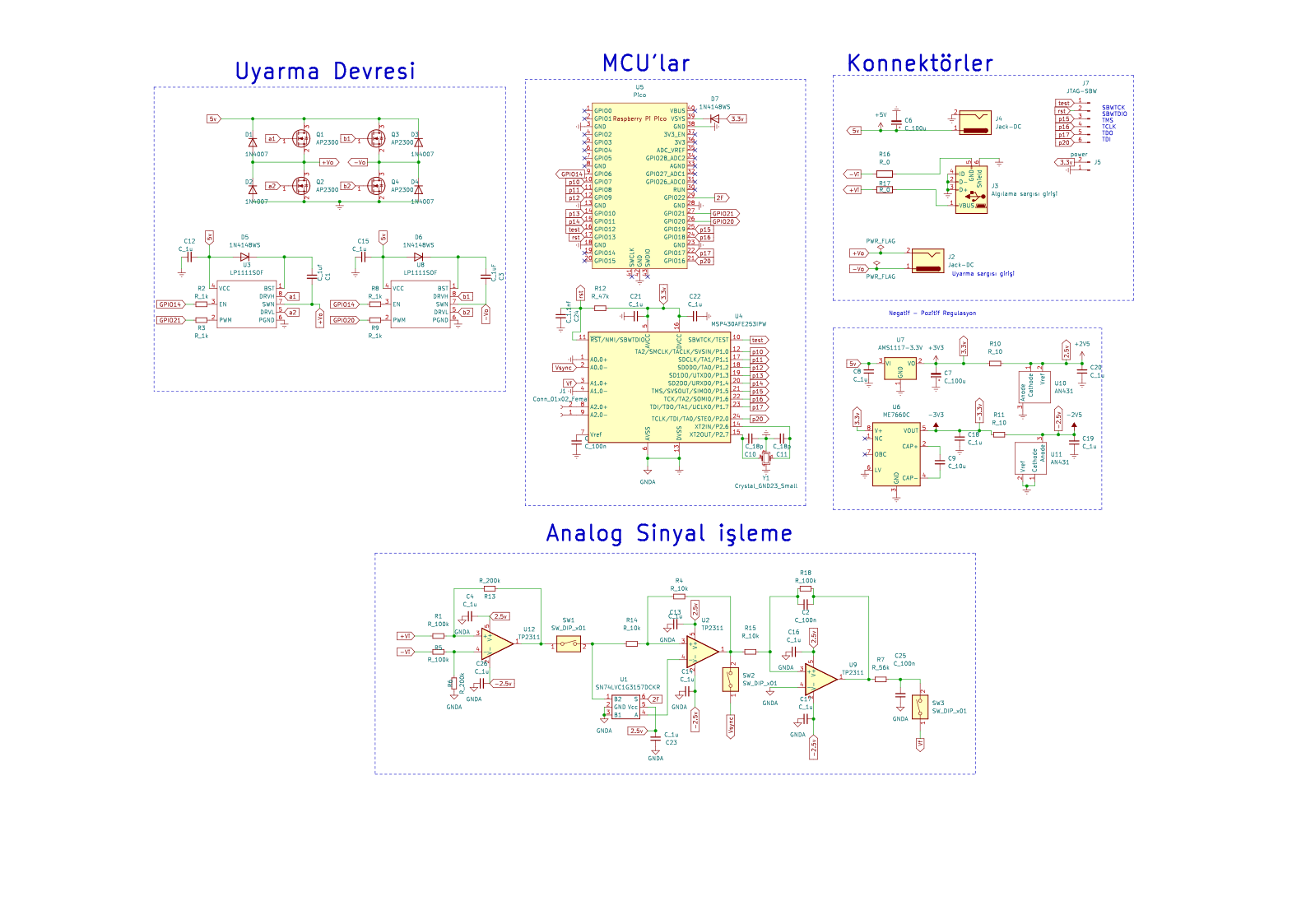
System Schematic Fig 1: Full system schematic diagram detailing all MCU pinouts, power distribution, and analog filters.
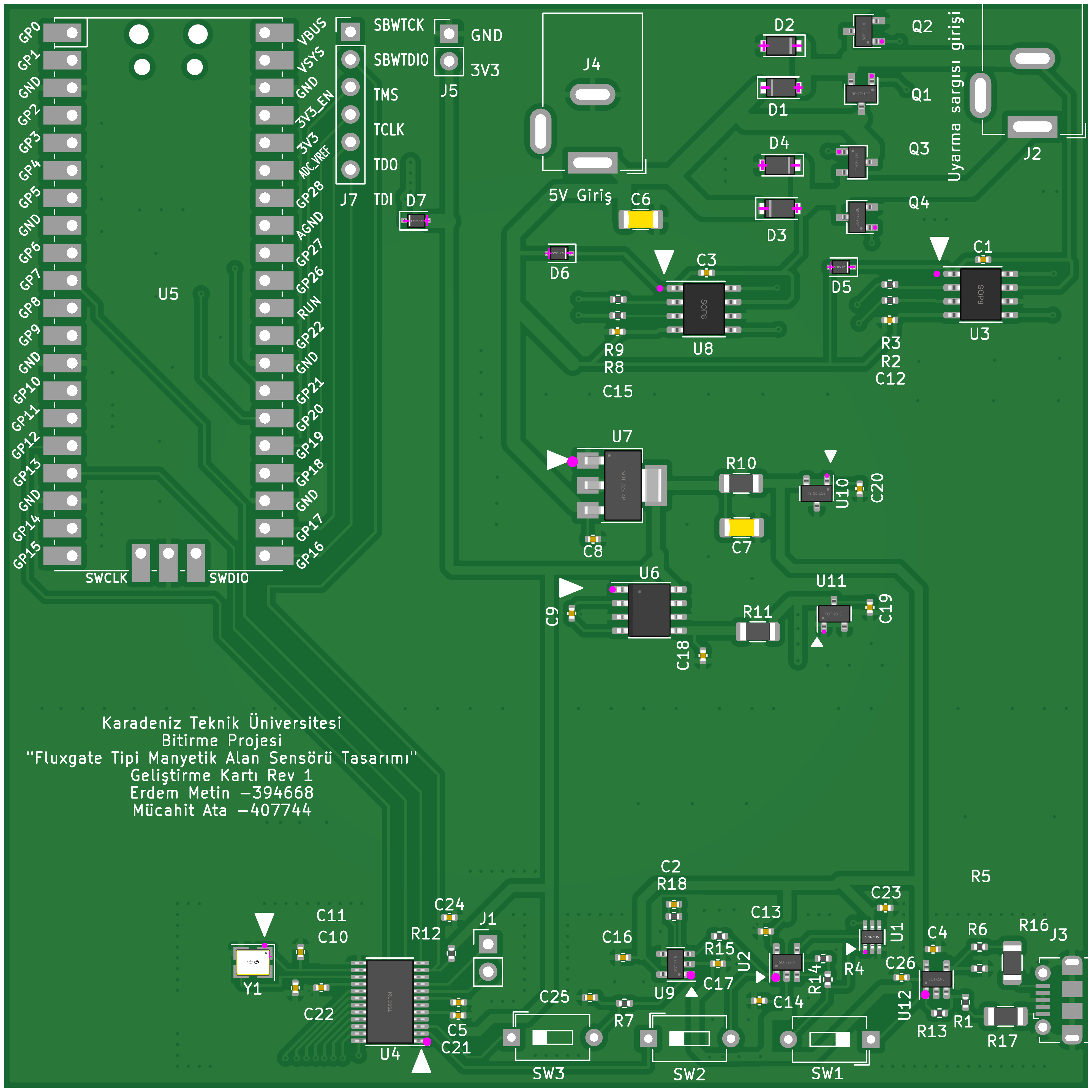
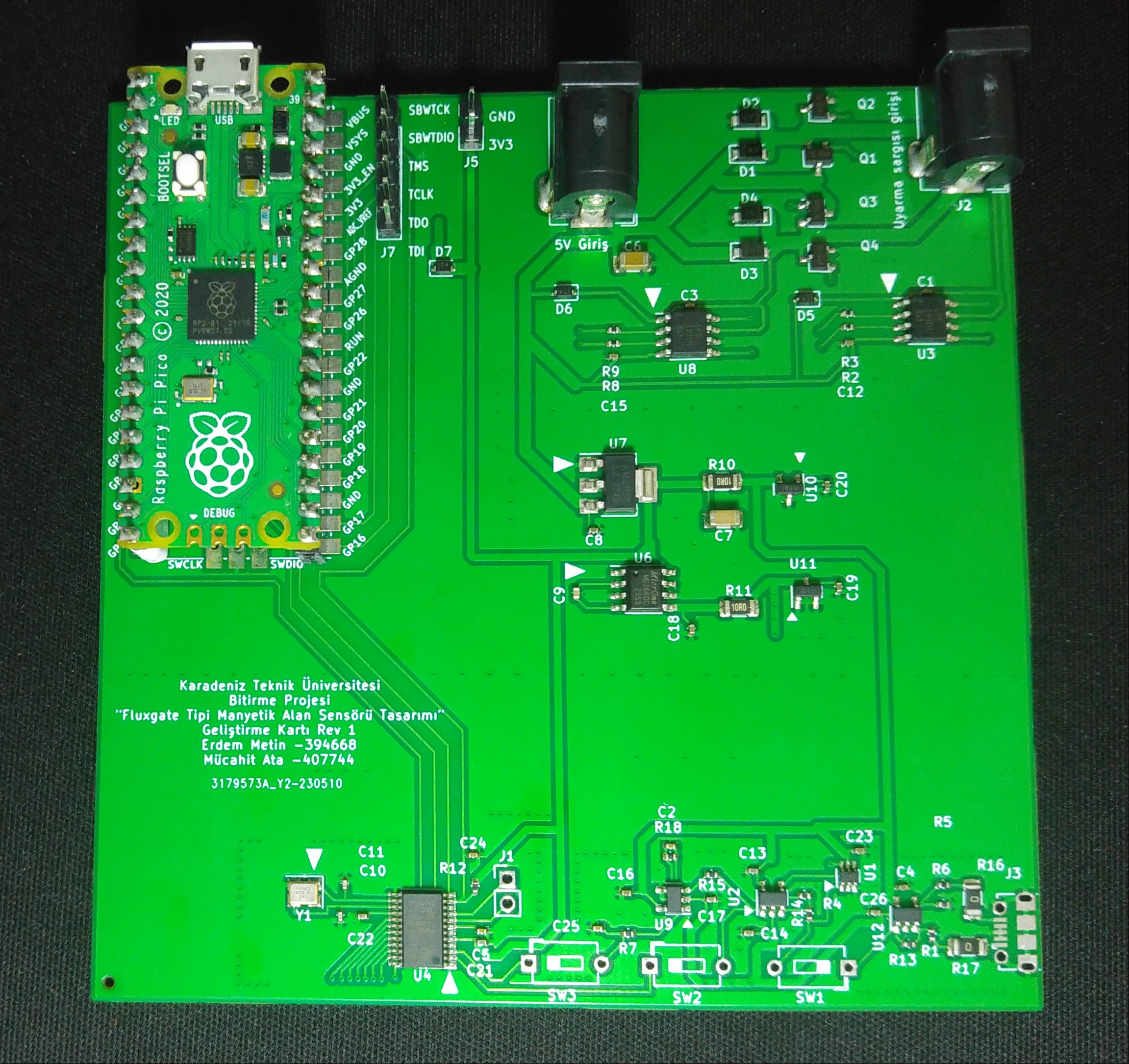
PCB Design Render Assembled Hardware Prototype

*Fig 2: KiCad PCB 3D layout render (left) and the fully assembled physical testing board (right).*
mermaid
graph TD
    PC[Computer PyQt GUI / Matlab] <-->|USB virtual COM / UDP Wifi| Pico[Raspberry Pi Pico RP2040]
    Pico -->|PWM Excitation Control f| FET[H-Bridge MOSFET Driver]
    FET -->|AC Excitation staircase Wave| Core[Magnetic Core & Coils]
    Core -->|Induced Sensing Signal| Demod[Analog Processing Circuit]
    Demod -->|DC Level / AC Signal| MSP[MSP430AFE253 24-bit ADC]
    MSP -->|1.5 MBaud UART| Pico

📖 Theory of Operation

A Fluxgate Magnetometer measures weak static or low-frequency magnetic fields (in the nT to µT range) by exploiting the non-linear magnetic saturation characteristics of a ferromagnetic core.

  1. Excitation (Drive): An AC current at frequency $f$ drives the core deep into saturation in both positive and negative directions.
  2. Symmetric Core State: In the absence of an external magnetic field, the magnetic flux changes symmetrically. The voltage induced in the sensing (pick-up) coil contains only odd harmonics ($3f$, $5f$, etc.).
  3. Asymmetric Core State (External Field Present): When an external magnetic field (like the Earth's field $H_{ext}$) is present, it biases the core, causing it to saturate earlier in one direction and later in the other.
  4. Second Harmonic (2f) Detection: This asymmetry generates even harmonics (predominantly the $2f$ component) in the sensing coil. The amplitude of this second harmonic is directly proportional to the magnitude of the external magnetic field, and its phase indicates the field's direction.

🛠️ Project Structure

The repository is structured into logically separated folders to make implementation and replication straightforward:

  • 📁 Hardware/ [blocked]: KiCad schematic and PCB layout designs, Gerber files, and Bill of Materials (BOM).
  • 📁 Firmware/ [blocked]:
    • MSP430: IAR and CCS projects for 24-bit Sigma-Delta ADC sampling at 16.5 kSps and 1.5 MBaud USART transmission.
    • RP2040 (Raspberry Pi Pico): C/C++ SDK projects generating precise excitation PWM and streaming data to PC via USB Serial or UDP Wi-Fi.
  • 📁 Software/ [blocked]: Python-based GUI utilizing pyqtgraph for real-time serial and UDP plotting, and Matlab analytics.
  • 📁 Simulations/ [blocked]: LTSpice circuits simulating the H-Bridge excitation driver and the analog synchronous demodulation path.

🚀 Step-by-Step Build & Replication Guide

To replicate and build this high-precision Fluxgate sensor, follow these five steps:

1. Hardware Fabrication & Assembly

  1. Go to Hardware/ [blocked] and select either the Excitation Circuit V1, the Excitation Circuit Final, or the JLCPCB Version which is optimized for SMT assembly.
  2. Export Gerbers or use the provided .zip files under the directories to order PCBs from your manufacturer (e.g., JLCPCB).
  3. Assemble the PCB using the BOM. Key components include:
    • Primary Controller: Raspberry Pi Pico (RP2040)
    • Precision ADC: MSP430AFE253IPW (24-bit Sigma-Delta ADC)
    • H-Bridge Driver: HIP4082xB half-bridge gate driver
    • Excitation MOSFETs: AP2300 or IRFZ44N
    • Ultra Low-Noise Opamps: TP2311 or LT149x series (12nV/√Hz input noise)
    • Voltage References: AN431 shunt regulators (2.5V, 20ppm/°C stability)

2. Fluxgate Core & Coil Preparation

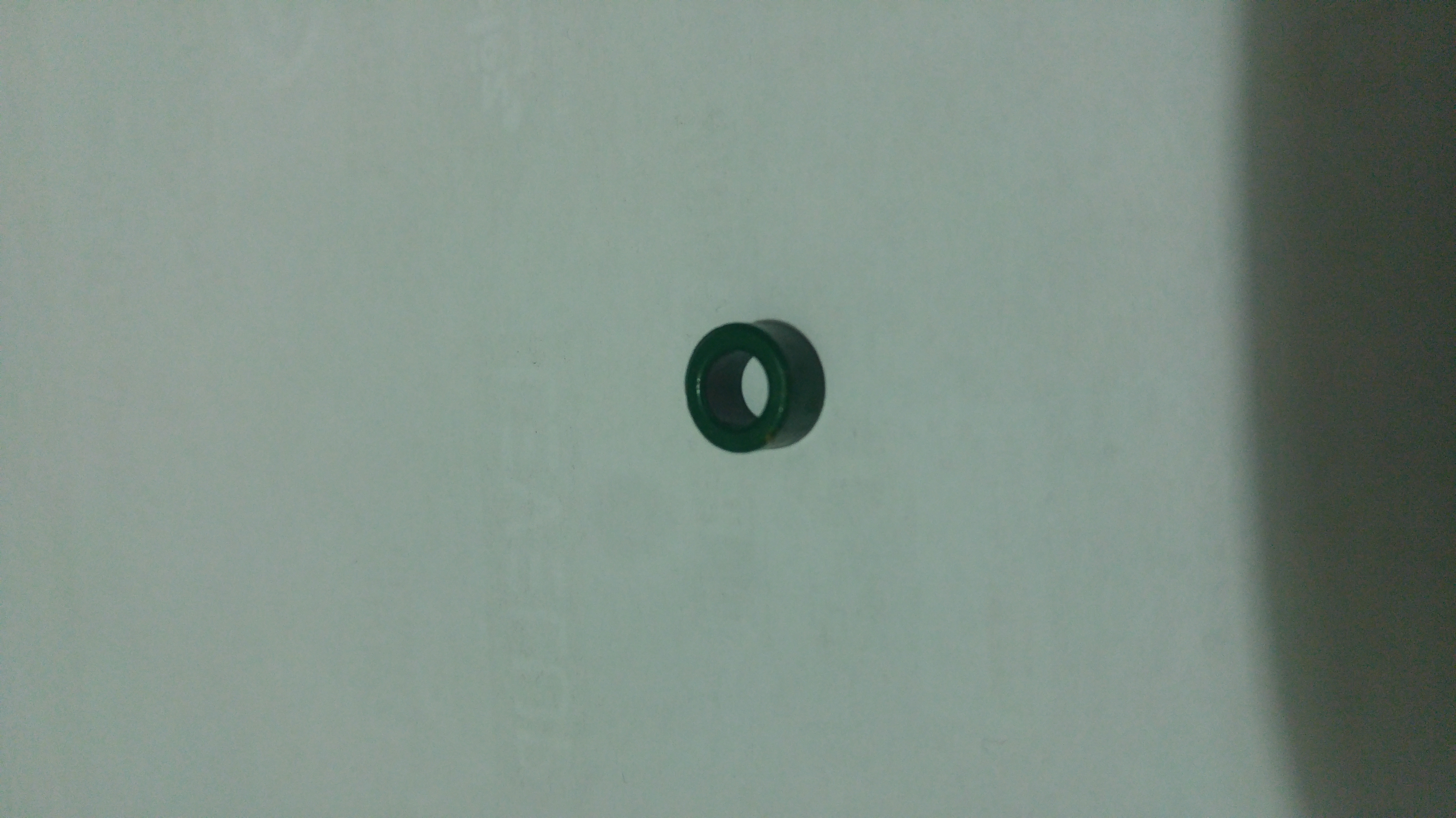
  1. Core Selection: Use a high-permeability green iron-powder ferrite toroid core with an inner diameter of 7 mm, thickness of 2 mm, and height of 4.5 mm. (While a 6-81 Permalloy racetrack core with $100\text{ µm}$ laminations provides lower noise, a toroidal ferrite core is robust and hand-windable).
  2. Drive Winding: Wind the excitation (drive) coil uniformly around the toroid using 32 AWG enameled copper wire. In the experimental prototype, the completed drive winding exhibited a measured series resistance of $17.945\text{ }\Omega$ and a series inductance of $19.686\text{ mH}$.
  3. Sense Winding: Wind the sensing (pick-up) coil on top of the drive winding, orienting the windings to capture the fluxgate effect while canceling direct coupling from the excitation drive.

Wound Fluxgate Core on Prototyping Board Fig 3: The custom hand-wound toroidal fluxgate core integrated onto the testing board.

3. Simulation & Validation

  1. Open Simulations/LTSpice/ [blocked].
  2. Run fluxgate.asc to simulate the H-Bridge excitation path. Verify the staircase voltage waveform across the drive bobbin.
  3. Run fluxgateACAnaliz.asc or Draft7.asc to analyze the frequency response of the active integrator and synchronous demodulator. Ensure the integration region lies between 159 Hz and 1591 Hz and the low-pass filter kesim frekansı is configured near 28 Hz.

4. Firmware Deployment

  1. MSP430 Firmware:
    • Open IAR Embedded Workbench or Code Composer Studio.
    • Load the project in Firmware/MSP430_AFE_ADC/ [blocked] or Firmware/MSP430_ADC_to_UART/ [blocked].
    • Compile and flash the firmware using an eZ-FET debugger (or the Spy-Bi-Wire pins on an MSP430 Launchpad).
    • Function: Configures the 12MHz MCLK, initializes the SD24 Module in group conversion mode, and streams 24-bit raw ADC readings via USART0 at 1.5M Baud.
  2. RP2040 Firmware:
    • Navigate to Firmware/Pico_Firmwares/ [blocked].
    • Choose either pico-custom-firmware-usb (USB Virtual Serial) or pico-custom-firmware-udp (Wi-Fi streaming).
    • Build the project using the Pico SDK (CMake) and flash the resulting .uf2 file onto your Pi Pico.
    • Function: Emits precise complementary PWM drive signals (80µs duty, 40µs dead-time) at frequency $f$ to drive the H-Bridge. It uses a PIO state machine to reliably capture the 1.5MBaud UART stream from the MSP430 and forwards it to the PC.

5. GUI & Visualization

  1. Install Python 3 and requirements:
    bash
    pip install pyqtgraph PyQt5 pyserial numpy
  2. Run the visualization app in Software/Python_GUI_Demo/ [blocked]:
    bash
    python compass.py
    # or
    python pyqtgraph_float_v2x2_yesim.py
  3. Connect your Pi Pico to the PC via USB. You will see a real-time rolling graph of the 24-bit sampled magnetic field data representing the external field.

📡 Digital Signal Processing (DSP) & Digital Lock-In Mode

During the final experimental testing phase of this project, the analog op-amps in the physical synchronous demodulation circuit were found to be defective or counterfeit, preventing analog phase detection from working out of the box. To solve this, the project utilized a highly robust Digital Signal Processing (DSP) pipeline to bypass the analog demodulator entirely.

Bypassing the Analog Demodulator

  1. The analog SPDT switch (SN74LVC1G3157) was disabled (tied to a static ground state via the MCU).
  2. The active low-noise op-amps were configured as a simple differential preamplifier.
  3. The raw, high-speed AC signal (which contains the even and odd harmonics) was fed directly into the MSP430's 24-bit Sigma-Delta ADC.
  4. The raw, un-demodulated samples were digitized at ~16.5 kSps and streamed to the PC via the RP2040 UART/USB bridge.

Two Host-Side Digital Processing Implementations

Your software repository implements two distinct mathematical approaches on the host PC to extract the external magnetic field from this raw stream:

  1. Frequency-Domain Demodulation (Real-Time FFT):

    • File: pyqtgraph_float_v2x2_yesim.py [blocked]
    • Method: Computes a high-performance Fast Fourier Transform (FFT) on blocks of 8192 raw samples using Scipy:
      python
      Yf0 = fft(ch0)
    • Result: The GUI displays the real-time frequency spectrum. By measuring the amplitude peak of the second harmonic ($2f$ at 25 kHz) in the frequency domain, the software calculates the precise external magnetic field intensity, completely replacing the physical analog lock-in filters!
  2. Time-Domain Smoothing (Moving Average Convolution):

    • Files: udp_plot_pyqt.py [blocked] and udp_plot_pyqt_2.py [blocked]
    • Method: Unpacks the high-speed telemetry and applies a real-time Moving Average Filter using NumPy convolution across a 1000-sample window:
      python
      filtered_data = np.convolve(data, weights, mode='valid')
    • Result: Smooths out the excitation switching ripples and transient spikes, feeding a clean time-domain signal to the graphical compass needle interface to dynamically show the core's magnetic orientation.

🛠️ Hardware Debugging & Engineering Solutions

During the assembly and testing phase, two critical engineering challenges arose and were systematically resolved:

1. The H-Bridge Bootstrap Capacitor & Duty Cycle Adaptation

  • The Issue: High-side gate drivers require a bootstrap capacitor ($C_{Bst}$) to maintain the gate-to-source voltage ($V_{GS}$) when the high-side MOSFET turns on. By design guidelines, the minimum bootstrap capacitance is: $$C_{Bst} = \frac{Q_{gate}}{\Delta V_{Bst}}$$ Using the AP2300 gate charge $Q_{gate} = 11\text{ nC}$ and an acceptable voltage ripple $\Delta V_{Bst} = 0.1\text{ V}$, the minimum capacitor required is $110\text{ nF}$. Due to a design oversight, a $1\text{ nF}$ capacitor was initially populated. This capacitor discharged instantly, causing the high-side gate drivers to drop out immediately.
  • The Fix: Populating a $1\text{ µF}$ capacitor resolved the gate-dropout issue. However, experimental tests under a $330\text{ }\Omega$ load revealed that the high-side gate could remain continuously open for a maximum of $1.125\text{ ms}$ before the bootstrap charge depleted.
  • PWM Adaptation: To prevent the high-side gate from collapsing during lower frequencies, the RP2040 firmware was adapted to emit a highly optimized PWM excitation pattern. Instead of a basic symmetrical square wave, the drive cycle was structured as:
    • $0.8\text{ ms}$ Positive Drive Phase (containing high-speed $80\text{ µs}$ pulses with $40\text{ µs}$ dead-times).
    • $0.4\text{ ms}$ Neutral Phase (H-bridge disabled, allowing the bootstrap capacitors to fully recharge).
    • $0.8\text{ ms}$ Negative Drive Phase (H-bridge reversed).

2. Defective Analog Op-Amps & DSP Bypass

  • The Issue: During board validation, short-circuiting the sensing coil to ground resulted in the low-noise differential preamplifier and active integrator output locks stuck at a solid $2.5\text{ V}$ (the virtual ground analog reference voltage). The op-amps (TP2311 or LT1492) failed to respond to any AC or DC input signal changes, leading to the conclusion that the physical components received were defective or counterfeit.
  • The Solution: The analog synchronous SPDT demodulator switch (SN74LVC1G3157) was set to ground mode via the RP2040, transforming the first stage into a simple, highly linear $1:2$ differential preamplifier (total differential gain of 20). The raw, high-speed AC pick-up signal was routed directly into the MSP430's 24-bit Sigma-Delta ADC, and the entire lock-in and filtering cascade was bypassed in hardware and reconstructed in real-time software on the host PC.

⚡ Specifications

ParameterValueDescription
Sensor TypeParallel FluxgateSingle Axis Magnetometer
Excitation WaveformAC Staircase WaveMinimizes transient EMF spikes
Excitation Frequency12.5 kHzConfigurable via Pico PWM registers
ADC Resolution24-BitSigma-Delta Converter (MSP430AFE253)
Sampling Rate~16,500 samples/secHigh-speed oversampled stream
Baud Rate1,500,000 BaudHigh-speed MSP430 to RP2040 UART link
Demodulator Gain1:10 (or 20 Differential)Synchronous analog SPDT demodulation
Low-Pass Filter (LPF)$f_c = 28.42\text{ Hz}$Eliminates grid noise (50Hz) and ripples
Integrator Bandwidth159 Hz to 1591 HzLimits noise and captures second harmonics

⚖️ License

This project is open-source and released under the MIT License [blocked]. Feel free to use, modify, and distribute for personal, academic, or commercial purposes.

Parts

77
QtyValueFootprintReferences
15C_1uCapacitor_SMD:C_0402_1005MetricC4, C8, C12, C13, C14, C15, C16, C17, C18, C19, C20, C21, C22, C23, C26
41N4007Diode_SMD:D_SOD-123FD1, D2, D3, D4
4AP2300Package_TO_SOT_SMD:TSOT-23Q1, Q2, Q3, Q4
4R_1kResistor_SMD:R_0402_1005MetricR2, R3, R8, R9
31N4148WSDiode_SMD:D_SOD-323D5, D6, D7
3C_1.1nfCapacitor_SMD:C_0402_1005MetricC1, C3, C24
3C_100nCapacitor_SMD:C_0402_1005MetricC2, C5, C25
3R_100kResistor_SMD:R_0402_1005MetricR1, R5, R18
3R_10kResistor_SMD:R_0402_1005MetricR4, R14, R15
3SW_DIP_x01Button_Switch_THT:SW_DIP_SPSTx01_Slide_6.7x4.1mm_W7.62mm_P2.54mm_LowProfileSW1, SW2, SW3
3TP2311Package_TO_SOT_SMD:SOT-23-5U2, U9, U12
2AN431Package_TO_SOT_SMD:SOT-23U10, U11
2C_100uCapacitor_SMD:C_1206_3216MetricC6, C7
2C_18pCapacitor_SMD:C_0402_1005MetricC10, C11
2Jack-DCConnector_BarrelJack:BarrelJack_GCT_DCJ200-10-A_HorizontalJ2, J4
2LP1111SOFPackage_SO:SOP-8_3.9x4.9mm_P1.27mmU3, U8
2R_0Resistor_SMD:R_1206_3216MetricR16, R17
2R_10Resistor_SMD:R_1206_3216MetricR10, R11
2R_200kResistor_SMD:R_0402_1005MetricR6, R13
1AMS1117-3.3VPackage_TO_SOT_SMD:SOT-223-3_TabPin2U7
1Algılama sargısı girişiConnector_USB:USB_Micro-B_Molex-105017-0001J3
1C_10uCapacitor_SMD:C_0402_1005MetricC9
1Conn_01x02_FemaleConnector_PinHeader_2.54mm:PinHeader_1x02_P2.54mm_VerticalJ1
1Crystal_GND23_SmallCrystal:Crystal_SMD_3225-4Pin_3.2x2.5mmY1
1JTAG-SBWConnector_PinHeader_2.54mm:PinHeader_1x06_P2.54mm_VerticalJ7
1ME7660CPackage_SO:SOP-8_3.9x4.9mm_P1.27mmU6
1MSP430AFE253IPWPackage_SO:TSSOP-24_4.4x7.8mm_P0.65mmU4
1PicoMCU_RaspberryPi_and_Boards:RPi_Pico_SMD_THU5
1R_47kResistor_SMD:R_0402_1005MetricR12
1R_56kResistor_SMD:R_0402_1005MetricR7
1SN74LVC1G3157DCKRPackage_TO_SOT_SMD:Texas_R-PDSO-G6U1
1powerConnector_PinHeader_2.54mm:PinHeader_1x02_P2.54mm_VerticalJ5

More from erdometo/fluxgate-project

2
  • 2 layers100 × 100 mmUyarma devresi (1), the printed circuit board in 3D

    Uyarma devresi (1)

    erdometo/fluxgate-project

    Open source fluxgate sensor project.

    67 parts3MIT
  • 2 layers149.9 × 99.1 mmUyarma devresi, the printed circuit board in 3D

    Uyarma devresi

    erdometo/fluxgate-project

    Open source fluxgate sensor project.

    46 parts3MIT

Similar boards

  • 4 layers91 × 30.1 mmStrelka Flight Computer, the printed circuit board in 3D

    Strelka Flight Computer

    LulaUAV/Strelka-Flight-Computer

    Strelka exists in the family of rocket dog flight computers. This flight computer is fully capable of deploying recovery events.

    170 parts2
  • 2 layers50 × 50 mmM5 USB Host v01, the printed circuit board in 3D

    M5 USB Host v01

    tomorrow56/M5Stack_USB_Host

    26 parts14AGPL-3.0
  • 2 layers191.5 × 76 mmPcb project, the printed circuit board in 3D

    Pcb project

    CrashOverride85/zc95

    4 channel EStim box inspired by the mk312bt, with Lua scripting support

    337 parts117GPL-3.0
  • 4 layers180 × 103.5 mmEEZ DIB DCP405plus, the printed circuit board in 3D

    EEZ DIB DCP405plus

    eez-open/dib-dcp405plus

    BB3+ Programmable 1-ch power module

    437 parts12
  • 4 layers68 × 68 mmBackbone, the printed circuit board in 3D

    Backbone

    andreapiccini/spaghettilab-community

    SpaghettiLab is an open modular hardware and software ecosystem for rapid prototyping, embedded systems development, and product innovation.

    212 parts10
  • 2 layers310 × 100 mmAOML AB 3.0 reorganized v2, the printed circuit board in 3D

    AOML AB 3.0 reorganized v2

    cxs1529/XBT_Autolauncher_PCB

    KiCAD repository for the XBT Autolauncher board

    247 parts
  • 4 layers104 × 64 mmFYDP, the printed circuit board in 3D

    FYDP

    mingzejin11/FYDP

    4B capstone project repository containing PCB design files

    259 parts

Questions

How big is the Uyarma devresi PCB?

It measures 100 × 100 mm and has 2 copper layers, 1.6 mm thick.

What parts does the Uyarma devresi use?

77 parts, built around the MSP430AFE253IPW, TP2311-TR, LP1111SOF and AMS1117-3.3V. The full list of its parts is on this page, with links to each part's symbol and footprint where PCBKit's library has them.

Where can I download the Uyarma devresi KiCad files?

From the erdometo/fluxgate-project repository on GitHub, at the commit this page was made from: the board is Hardware/KiCad_Development_Board_JLCPCB/uyarma devresi.kicad_pcb and its schematic Hardware/Excitation_Circuit_V1/uyarma devresi.kicad_sch. PCBKit opens the board in the browser, with nothing to install.

Can I use the Uyarma devresi design in my own project?

Its repository publishes it under the MIT licence: you may reuse it on that licence's terms (keep the author's notice, and for a copyleft licence share your changes alike).