Skip to the content
2 layers100.6 × 50 mmDisplay unit2, the printed circuit board in 3D

Semanur and I are university students at METU EE, and we are lab partners at an analog laboratory course abbreviated as EE313. In this course, we do predetermined experiments on analog circuits (mainly amplifiers). At the end of the term, we are supposed to design a prototype that fulfills a specified task. This repo will include files of that prototype.

Size
100.6 × 50 mm
Copper layers
2
Thickness
1.6 mm
Parts
45
Nets
34
Pads
109
Tracks, vias
329, 2
Pours
1
Routed
Yes
KiCad
KiCad 5 (file 20171130)
Created
2 Jan 2022
Updated
16 Feb 2022

Overview

Display unit2 is an open-source printed circuit board by erdemcanaz, from the erdemcanaz/EE313-Term-project repository on GitHub. It is a 2-layer board of 100.6 × 50 mm with 45 parts on 34 nets, routed with 329 tracks and 2 vias.

It is built around the LM358 and BC547. Its parts include 30 resistors, 7 diodes, 3 transistors, 3 connectors and 2 ICs. It belongs with the lEDs and displays boards of this library.

Main components

2

README

README.md

Implementing An Analog Approach For Closed Environment Autonomous Temperature Control Circuitry

EE-313 TERM PROJECT

General requirements

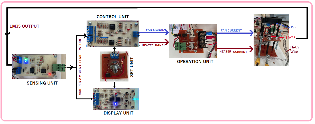
The project consists of five units; namely, sensing, set, control, operation and display units. The sensing unit perceives the ambient temperature and sends this information to the control and display units. Similarly, set unit receives an input from the user indicating the desired temperature level and send this information to control and display units. Control unit compares the two temperatures and decides the action to be taken by the operation unit. Operation unit is where the heating and cooling systems are present. It perates one of these systems according to the signal sent from the control unit. Display unit shows the ambient and set temperatures by mapping them into a color spectrum
Sensing Unit
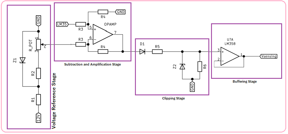
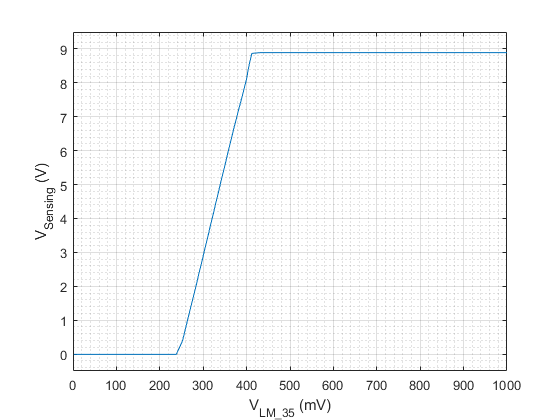
Sensing unit output voltage (Vsensing) is 0V and 9V voltage for the 24◦C and 40◦C temperatures, respectively. Between these temperature levels, it has a linear increase in the output voltage. Outside of this temperature range, it performs clipping in the voltage levels. The temperature sensor used (LM35) has lienar characteristics and outputs 240mV and 400mv for 24◦C and 40◦C temperatures respectively. By subtracting 240mV and multiplying the result with 56 (160 mV x 56=8.96V), we can get desired output characteristics. Yet another problem to solve is to constrain this voltage in between 0-9Volts. Which can be done by a diode an a 9.1V zenner diode.

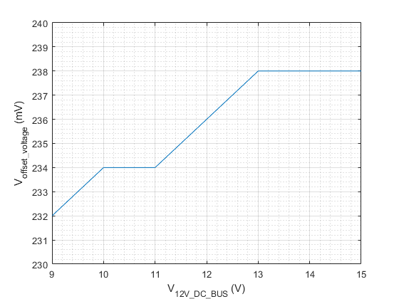
  1. Voltage Reference Stage: At this stage, about 240mV+(0.7)/56 is generated. 240mV is due to LM35 and (0.7)/56 is due to forward voltage drop of diode D1. Even though R3 & R4 is >> R1,R2 % R_POT; this voltage reference is not isolated. Also forward votlage drop of the diode may not be exactly 0.7Volts. Thus, a potentiometer is used to find exact point where output is 0 volt at 24C and starts to increase just after that. Then, potentiometer is replaced by resistors.
  2. Subtraction and Amplification Stage: At this stage, reference voltage is subtracted froum LM35 voltage output. The result is multiplied by the ratio of R4/R3. We chosed R4/R3 as 56.
  3. Clipping Stage: This stage rectifies the output of the subtraction stage due to D1. And if voltage of the previous stage is greater than V_Z2, Z2 is activated and voltage upper limit is set.
  4. Buffering Stage: This stage buffers the output.
Experimentally measured input output characteristics and stability of the reference stage due to unstable buss voltage are given below.
Set Unit

Desired temperature is set by adjusting the the potentiometer's knob. The schematic is self explanatory. R1, R2 and R_POT ensures voltage of the second leg of the potentiometer is greater than 0.25V and less than 8.75V.
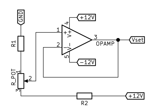
Control Unit
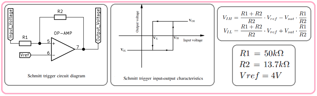
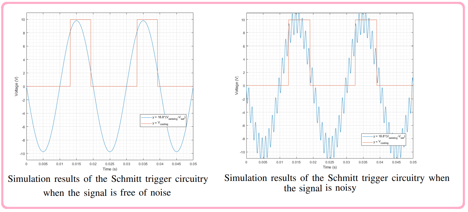
Operation Unit: Heating and Cooling

Display Unit

THANKS!
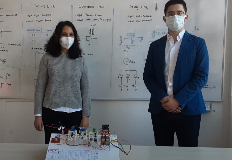
Semanur Avşar (Left) & Erdem Canaz (right)
https://youtu.be/WysXOD-1qQ8

Parts

45
QtyValueFootprintReferences
6100kResistor_THT:R_Axial_DIN0309_L9.0mm_D3.2mm_P12.70mm_HorizontalR6, R10, R11, R12, R19, R21
3200kResistor_THT:R_Axial_DIN0309_L9.0mm_D3.2mm_P12.70mm_HorizontalR14, R16, R17
365kResistor_THT:R_Axial_DIN0309_L9.0mm_D3.2mm_P12.70mm_HorizontalR22, R25, R29
3700Resistor_THT:R_Axial_DIN0309_L9.0mm_D3.2mm_P12.70mm_HorizontalR23, R24, R30
3BC547Package_TO_SOT_THT:TO-92L_Inline_WideQ1, Q2, Q3
20Resistor_THT:R_Axial_DIN0309_L9.0mm_D3.2mm_P12.70mm_HorizontalR8, R9
2100Resistor_THT:R_Axial_DIN0309_L9.0mm_D3.2mm_P12.70mm_HorizontalR26, R27
22kResistor_THT:R_Axial_DIN0309_L9.0mm_D3.2mm_P12.70mm_HorizontalR3, R4
26.8VDiode_THT:D_A-405_P12.70mm_HorizontalD1, D2
2880Resistor_THT:R_Axial_DIN0309_L9.0mm_D3.2mm_P12.70mm_HorizontalR18, R20
2DDiode_THT:D_A-405_P12.70mm_HorizontalD3, D5
2LM358Package_DIP:DIP-8_W7.62mmU1, U2
11.5kResistor_THT:R_Axial_DIN0309_L9.0mm_D3.2mm_P12.70mm_HorizontalR1
110kResistor_THT:R_Axial_DIN0309_L9.0mm_D3.2mm_P12.70mm_HorizontalR7
12.2kResistor_THT:R_Axial_DIN0309_L9.0mm_D3.2mm_P12.70mm_HorizontalR2
1300Resistor_THT:R_Axial_DIN0309_L9.0mm_D3.2mm_P12.70mm_HorizontalR28
13kResistor_THT:R_Axial_DIN0309_L9.0mm_D3.2mm_P12.70mm_HorizontalR13
150kResistor_THT:R_Axial_DIN0309_L9.0mm_D3.2mm_P12.70mm_HorizontalR5
17kResistor_THT:R_Axial_DIN0309_L9.0mm_D3.2mm_P12.70mm_HorizontalR15
1Conn_01x02_FemaleTerminalBlock:TerminalBlock_Altech_AK300-2_P5.00mmJ3
1Conn_01x03_FemaleConnector_PinHeader_2.54mm:PinHeader_1x03_P2.54mm_VerticalJ1
1Conn_01x03_FemaleTerminalBlock:TerminalBlock_Altech_AK300-3_P5.00mmJ2
1RGB_LED_ANODEConnector_PinHeader_2.54mm:PinHeader_1x04_P2.54mm_VerticalD7
1blueLED_THT:LED_D3.0mm_FlatTopD6
1redLED_THT:LED_D3.0mm_FlatTopD4

More from erdemcanaz/EE313-Term-project

2
  • 2 layers100.3 × 50 mmControl unit4, the printed circuit board in 3D

    Control unit4

    erdemcanaz/EE313-Term-project

    Semanur and I are university students at METU EE, and we are lab partners at an analog laboratory course abbreviated as EE313. In this course, we do predetermined experiments on analog circuits (mainly amplifiers).

    38 parts1
  • 2 layers100.3 × 50.3 mmSensing unit1, the printed circuit board in 3D

    Sensing unit1

    erdemcanaz/EE313-Term-project

    Semanur and I are university students at METU EE, and we are lab partners at an analog laboratory course abbreviated as EE313. In this course, we do predetermined experiments on analog circuits (mainly amplifiers).

    25 parts1

Similar boards

  • 2 layers132.1 × 45.7 mmIPoS, the printed circuit board in 3D

    IPoS

    peterheinrich/InternetOverSpaghetti

    Transmitting IP packages over a pair of spaghetti thus demonstrating how media independent IP really is.

    42 parts342
  • 2 layers76 × 100 mmVclfo10, the printed circuit board in 3D

    Vclfo10

    EchelonForce/vclfo10

    A Eurorack LFO design based on the Electric Druid VCLFO10 chip.

    139 parts7
  • 2 layers123.8 × 99.7 mmThc, the printed circuit board in 3D

    Thc

    festlv/thc

    An automatic torch height controller

    75 parts7
  • 2 layers206.2 × 138.1 mmOric, the printed circuit board in 3D

    Oric

    Board-Folk/Oric-Remix

    Oric Remix

    133 parts4
  • 2 layers38 × 100 mmVca as3360-circuit, the printed circuit board in 3D

    Vca as3360-circuit

    fledsbo/Modules

    Eurorack module designs using KiCad — VCO, VCF, VCA, ADSR, and Daisy Seed

    74 parts3
  • 2 layers55 × 485 mmFg lampe, the printed circuit board in 3D

    Fg lampe

    devtal-de/fg_lampe

    181 parts1
  • 4 layers140 × 136 mmVinyl adc rev d, the printed circuit board in 3D

    Vinyl adc rev d

    MadsRudolph/vinyl-adc

    Discrete 3rd-order delta-sigma stereo audio ADC, built from op-amps and logic gates: a four-layer Raspberry Pi HAT made by PCBWay, with KiCad files, SPICE simulations and measurements

    184 parts1

Questions

How big is the Display unit2 PCB?

It measures 100.6 × 50 mm and has 2 copper layers, 1.6 mm thick.

What parts does the Display unit2 use?

45 parts, built around the LM358 and BC547. The full list of its parts is on this page, with links to each part's symbol and footprint where PCBKit's library has them.

Where can I download the Display unit2 KiCad files?

From the erdemcanaz/EE313-Term-project repository on GitHub, at the commit this page was made from: the board is KiCad/display unit3/display unit2.kicad_pcb. PCBKit opens the board in the browser, with nothing to install.

Can I use the Display unit2 design in my own project?

Its repository states no licence, so its author keeps all rights: ask erdemcanaz before reusing the design.