

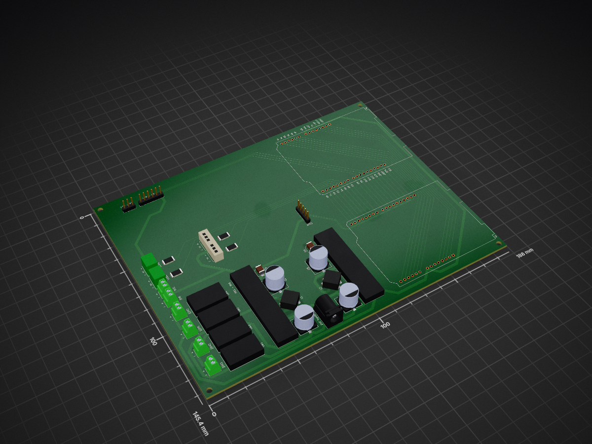
Sleep rig pcb
- Size
- 188 × 145.4 mm
- Copper layers
- 2
- Thickness
- 1.6 mm
- Parts
- 34
- Nets
- 54
- Pads
- 167
- Tracks, vias
- 283, 0
- Pours
- 1
- Routed
- Yes
- KiCad
- KiCad 7 (file 20221018)
- Created
- 20 Feb 2024
- Updated
- 11 Oct 2024
Overview
Sleep rig pcb is an open-source printed circuit board by EPL-Engineering, from the EPL-Engineering/sleep_rig repository on GitHub. It is a 2-layer board of 188 × 145.4 mm with 34 parts on 54 nets, routed with 283 tracks and 0 vias.
It is built around the ARDUINO UNO R3, NID100-12 and NID100-5, with the L101011MS02Q, RPC2512JT220R and CMS1-4-R among its other parts. Its parts include 6 capacitors, 4 resistors, 4 switches, 2 connectors and 2 inductors. It belongs with the AVR (ATmega, ATtiny) boards of this library.
Main components
8ARDUINO UNO R3
Arduino UNO R3 Printed Circuit Board ModuleArduinoUncategorisedNID100-12
SIP,50.8x12mm1 12V 20V~53V 7.5A 96% SIP,50.8x12mm Power Module/Power Supply ROHSMWDC-DC Power ModulesNID100-5
-- Power Module/Power Supply ROHSMWPower Module/Power SupplyL101011MS02Q
插件-30℃~+65℃ 28V Rectangular Columnar SPST Through Hole 插件 Slide Switches ROHSC&KSlide SwitchesRPC2512JT220R
2512-55℃~+155℃ 1.5W 220Ω Thick Film Resistor ±100ppm/℃ ±5% 2512 Chip Resistor - Surface Mount ROHSStackpole Electronics (SEI)Chip Resistor - Surface MountCMS1-4-R
SMD-4P,9.4x7.2mm-40℃~+160℃ 18uH@100kHz 2 3.8A 300V 8.9mΩ SMD-4P,9.4x7.2mm Common Mode Filters ROHSEatonCommon Mode FiltersEEEFK1V220R
SMD,D5xL5.8mm-55℃~+105℃ 120mA@120Hz 2000hrs@105℃ 22uF 35V 5mm 6.1mm Polarized ±20% SMD,D5xL5.8mm Aluminum Electrolytic Capacitors - SMD ROHSPanasonicAluminum Electrolytic Capacitors - SMDPJ-002BH
插件-25℃~+85℃ 2.5mm 24V 5A 6.5mm DC Power Jack Right Angle 插件 DC Power Connectors ROHSCUIDC Power Connectors
README
README.mdEnvironment Monitor
TODO
- Save state across serial reconnects (desolder RST ENABLE)
- Finish chart display for log data
- Cleanup upon application exit
Hardware Setup
- Plug in the red/yellow/black climate sensor cables to the 3-pin molex connectors on the PCB (DHT1 and DHT2 labels on PCB)
- Using a precision flathead, screw the wires from the LED strips into the terminal blocks of the PCB (LED1 and LED2 labels on PCB)
- Red wire goes to '+' terminal
- Black wire goes to '-' terminal
- Colored wire (blue/green) goes to 'D' terminal
- Connecting the wires in the wrong configuration will fry the entire LED strip
- Optional: connect the positive and negative leads of the box fan to either the 24V or 12V onboard switches, depending on fan specs
- Double check all of your connections and make sure the positive and negative terminals are always hooked up to a red and black wire, respectively
- Plug in 24V power source to the barrel jack on the PCB (DO NOT PLUG 24V INTO THE ARDUINO BARREL JACK — ONLY USE ONBOARD JACK)
- Plug USB-B into the Arduino and connect other end to PC where GUI is running
Connecting to Serial
- Run EnvironmentMonitor.exe located in the main folder of this repo
- Select the COM port that is tied to the Arduino and click connect
- Arduino will reset all settings when the serial connection is reconnected
- Arduino is ready when "SER_CON" event is pinged back
Auto LED Timer
- Specify a day start and day stop time in 24HR clock format (make sure day start comes before day end chronologically, or bugs may occur)
- Simply click start to initiate the day/night cycling (white light starts at day start time and red light at day end)
- Click stop at any time to cancel the day/night cycling and turn of the LEDs (do this before disconnecting the serial port)
Manual Color Control
- Select color and click send to manually control LED color; LEDs will behave according to most recent data sent (e.g. manual control will change the color even when day/night cycle is running)
- Enter integer number between 0-255 to adjust the brightness of both LED strips; brightness setting is the same for both boxes despite two separate controls
Serial Monitor
- Every 15 minutes or upon any command entry, the Arduino will send a packet with sensor data from both boxes
- Data is formatted as a string and written to both a log.txt file inside the repo and the serial monitor display
- A new log file is opened upon serial connect; disconnecting serial or closing the window will save the file
- Log files will append an increasing integer to filename to avoid overwriting
Special Notes
- To avoid bugs, always disconnect the serial port before closing the application
- The Arduino will restart if it reconnects to serial, but it will continue running at disconnect (e.g. you can enable auto day/night cycles and it will continue to run if you disconnect serial port; it will reset and turn off when you reconnect to serial)
- Boxes can be run independently, but log entries will still track both
- Default brightness is set to 1; you will need to increase this
Parts
34| Qty | Value | Footprint | References |
|---|---|---|---|
| 4 | EEE-FN1J121UP | 120uF_cap:CAP_FN_G_PAN | C1, C2, C4, C5 |
| 4 | L101011MS02Q | switch:SW_1MS02Q_CNK | SW1, SW2, SW3, SW4 |
| 4 | RPC2512JT220R | smd_220_res:STA_RPC2512_STP | R1, R2, R3, R4 |
| 2 | 12V | terminal_block_bi:TE_282834-2 | 12V1, 12V2 |
| 2 | 5V | terminal_block_bi:TE_282834-2 | 5V1, 5V2 |
| 2 | Arduino_UNO_R3 | Module:Arduino_UNO_R3 | A1, A2 |
| 2 | CMS1-4-R | choke:CMS1 | L1, L2 |
| 2 | EEEFK1V220R | 22uF_cap:CAP_EEEFK1V220R | C3, C6 |
| 1 | DHT1 | molex_tri:MOLEX_0022272031 | DHT1 |
| 1 | DHT2 | molex_tri:MOLEX_0022272031 | DHT2 |
| 1 | FAN1 | terminal_block_bi:TE_282834-2 | 24V1 |
| 1 | FAN2 | terminal_block_bi:TE_282834-2 | 24V2 |
| 1 | LCD - P1 | Connector_PinHeader_2.54mm:PinHeader_1x03_P2.54mm_Vertical | LCD - P1 |
| 1 | LCD - P2 | Connector_PinHeader_2.54mm:PinHeader_1x06_P2.54mm_Vertical | LCD - P2 |
| 1 | LED1 | terminal_block_tri:CONN_282834-3_TYC | J4 |
| 1 | LED2 | terminal_block_tri:CONN_282834-3_TYC | J5 |
| 1 | NID100-12 | dc_regulator:CONV_NID100-5 | PS2 - 12V1 |
| 1 | NID100-5 | dc_regulator:CONV_NID100-5 | PS1 - 5V1 |
| 1 | PJ-002BH | barrel_jack:CUI_PJ-002BH | 24V Input1 |
| 1 | RTC | Connector_PinHeader_2.54mm:PinHeader_1x05_P2.54mm_Vertical | RTC1 |
Questions
How big is the Sleep rig pcb PCB?
It measures 188 × 145.4 mm and has 2 copper layers, 1.6 mm thick.
What parts does the Sleep rig pcb use?
34 parts, built around the ARDUINO UNO R3, NID100-12, NID100-5 and L101011MS02Q. The full list of its parts is on this page, with links to each part's symbol and footprint where PCBKit's library has them.
Where can I download the Sleep rig pcb KiCad files?
From the EPL-Engineering/sleep_rig repository on GitHub, at the commit this page was made from: the board is hcam_environment_monitor_pcb/hcam_environment_monitor_pcb/sleep_rig_pcb.kicad_pcb and its schematic hcam_environment_monitor_pcb/hcam_environment_monitor_pcb/sleep_rig_pcb.kicad_sch. PCBKit opens the board in the browser, with nothing to install.
Can I use the Sleep rig pcb design in my own project?
Its repository states no licence, so its author keeps all rights: ask EPL-Engineering before reusing the design.
Similar boards
- 4 layers249.5 × 95 mm
- 2 layers87.5 × 100 mm

PCB Ventil
reivax-boucoi/PCB_Kicad
Repo for all my home projects involving PCBs developped with Kicad
58 parts1 - 2 layers64.8 × 50.5 mm

- 6 layers92.6 × 69.4 mm

Usb hub 2
yedidia-sisay/usb3-multiport-hub
An open-source USB 3.2 Gen 2 (10 Gbps) multiport hub & docking station.
230 parts - 4 layers59.7 × 70 mm

- 2 layers60 × 60 mm

- 2 layers

- 2 layers63.9 × 89.2 mm

Ab rec
LJWsao/sinitsa
KiCAD files for the all band receiver. This can pick up strong local sources of RF such as AM and FM radio stations.
47 parts1