2 layers252.9 × 77.6 mm
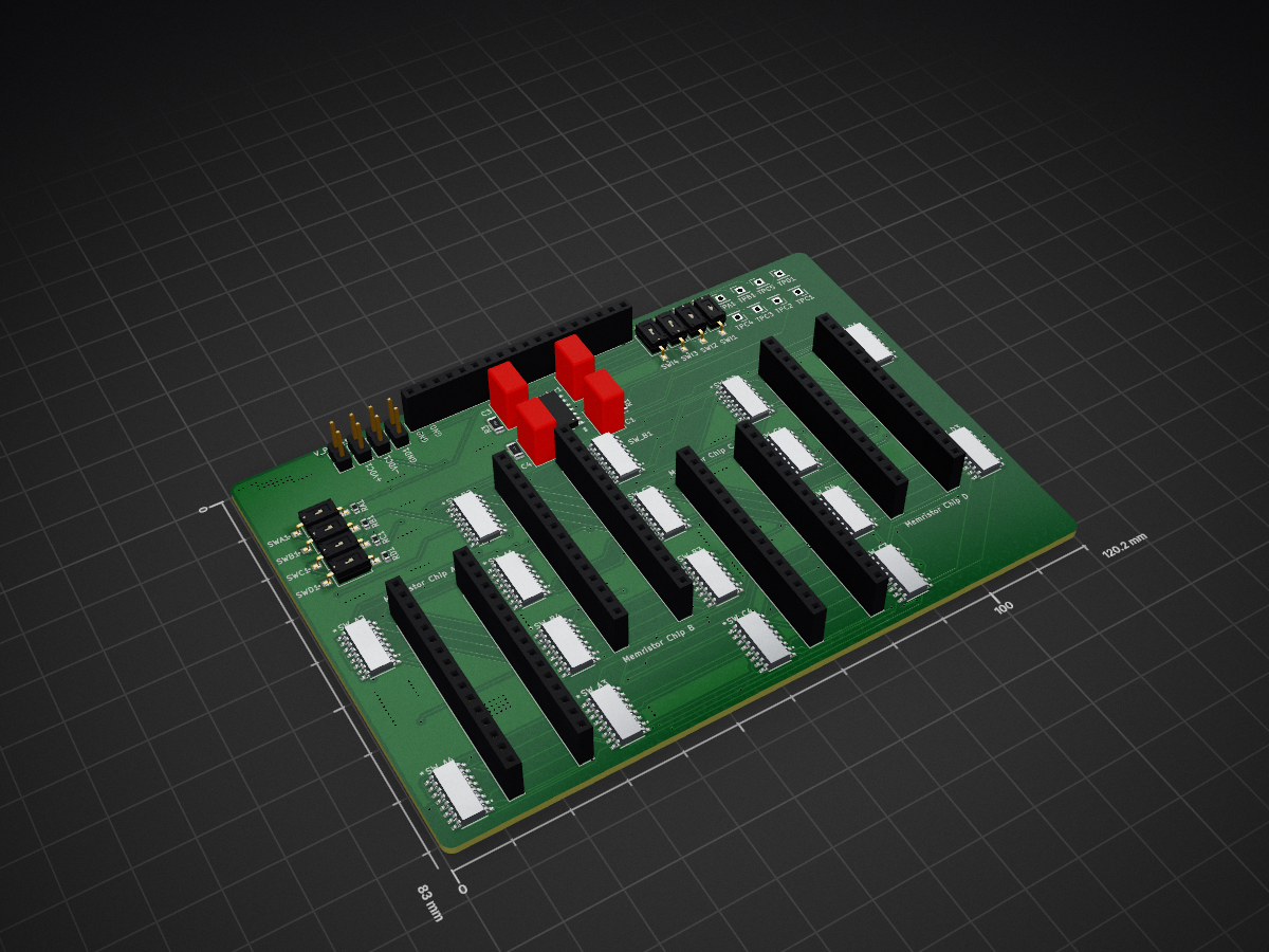
 EPIC-Lab-UT/ANCHOR2
Open-source mixed-signal neuromorphic hardware platform built with COTS Knowm memristors. Includes the 16x4 array PCB design, control software, weight-derivation notebooks, and two labelled temporal classification datasets.
Memristor Board PCI is an open-source printed circuit board by EPIC-Lab-UT, from the EPIC-Lab-UT/ANCHOR repository on GitHub. It is a 2-layer board of 120.2 × 83 mm with 58 parts on 104 nets, routed with 1,828 tracks and 354 vias.
It is built around the OPA4140AID and DG444DY+. Its parts include 8 connectors, 4 capacitors and 4 resistors.


A COTS Memristor Hardware Platform for Temporal Signal Classification
An open-source mixed-signal platform that classifies temporal sensor signals using a physical 16×4 array of commercial off-the-shelf memristors on a standard PCB. Weights are stored as programmable resistance states and the computation happens in the signal path. No custom fabrication, no foundry access, and no digital multiply–accumulate.
New to this? A memristor is a resistor whose resistance you can set electrically, and which keeps that value when the power is removed. That makes it a memory cell and a multiplier at once: apply a voltage and Ohm's law does the arithmetic where the number is stored, instead of shuttling it to a processor first. That idea is called in-memory computing, and hardware built to compute the way nervous systems do is called neuromorphic.
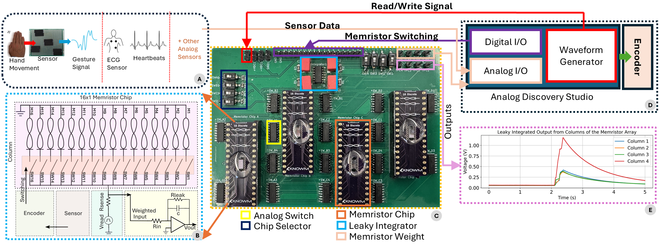
The array is built from commercial Knowm self-directed-channel memristors, sold as discrete parts with no foundry access required.
An encoder maps signal amplitude to one of 16 array rows. Each selected row is read through a voltage divider, producing four resistance-weighted class voltages; four RC leaky integrators accumulate them over time, and the class is whichever integrator ends highest.
Note on the architecture. The encoder selects at most one row per sample, so ANCHOR does not perform a simultaneous full-vector crossbar operation. Temporal memory comes from the integrator decay, not from parallel matrix–vector multiplication. This is a deliberate design choice: it is what lets a 16×4 array of individually addressable COTS devices classify time-varying signals.
| Stage | Where it happens |
|---|---|
| 1. Amplitude encoding: the waveform is quantised into 16 amplitude levels that map one-to-one onto array rows | Software + ADS digital I/O |
| 2. Memristor weighting: the selected row is read at −80 mV through a 10 kΩ sense resistor, producing four class voltages | Analog, in the signal path |
| 3. Leaky integration: four RC integrators accumulate the column voltages, so older contributions decay | Analog, on-board |
| 4. Decision: the class is the highest final integrator voltage | Oscilloscope |
Encoding is event-driven: a row activates when the signal enters its amplitude band and changes only when the signal crosses a threshold. A dead band around zero means an idle signal starts no computation. There is no clock.
| Task | Classes | Held-out accuracy | Per-class recall | Array read-path power |
|---|---|---|---|---|
| Directional hand gestures | 4 | 87% (100 signals) | BT 92 · LR 88 · TB 84 · RL 84 | 30.35 µW |
| ECG heartbeat classification | 4 | 85% (51 of 60) | RBBB 100 · PB 93.3 · NB 80 · VFW 66.7 | 25.86 µW |
Both tasks run on the same 64 devices, reprogrammed between them. Gesture errors occur only within the BT/TB and LR/RL pairs; none crosses between vertical and horizontal gestures.
What these accuracies measure. Held-out windows, not held-out recordings. The gesture segments were cut from nine continuous recordings and every recording contributes windows to both training and test, so 87% describes separability on this hardware, not generalisation to a new session, performer, or lighting. Each ECG class is drawn from a single MIT-BIH record, so 85% is likewise not patient-generalisation accuracy.
Power figures are peak-current-based estimates of the memristor read paths only; they exclude the ADS, computer, oscilloscope and integrator circuits.
Where these numbers come from. They are the hardware measurements reported in the ANCHOR paper, taken under its protocol: 40 training signals per class, with 25 gesture signals and 15 heartbeats per class held out for the hardware test. This repository ships a larger curated dataset (436 gesture segments, 637 beats) with its own train/validation/test manifests, so re-running the notebooks will not reproduce these exact figures. The test counts match (100 and 60); the training pools do not.
ANCHOR/
├── Docs/
│   └── User_Manual.md              build it, program it, run it - start here
├── Hardware/PCB_Design/
│   └── Memristor_Board_DIP/        KiCad schematic + layout, Gerbers, BOM, 3D models
├── Software/
│   ├── Memristor_Array_Weights/    Python notebooks - derive the resistance matrix
│   └── System_Operation/           C++ programs - program the array, run inference
├── Dataset/
│   ├── Hand_Gesture_Dataset/       436 recordings, 4 classes  (CC BY 4.0)
│   └── ECG_Heartbeat_Dataset/      637 MIT-BIH beats, 4 classes  (ODC-BY 1.0)
├── Webpage/                        project page, relative image paths
└── Images/→ Read Docs/User_Manual.md. It covers the hardware, the
components, assembly, and three tutorials that take you from raw sensor data to a
class voltage on the oscilloscope.
The short version:
| Step | Tool | What happens |
|---|---|---|
| 1. Derive weights | Software/Memristor_Array_Weights/*.ipynb | Encode the training data, optimise a 16×4 resistance matrix, export per-class target CSVs |
| 2. Program the array | Set_Weights.exe | Closed-loop read–verify–write drives all 64 devices to target |
| 3. Run inference | Inference_Read_Set_Weights.exe | Replays the test split through the array via the ADS; four class voltages come out |
numpy / pandas / matplotlibBuild the C++ side with Software/System_Operation/ANCHOR.sln (Release | x64).
Both are included in full, with fixed train/validation/test splits that the notebooks
assert are disjoint before doing any work. The test split is reserved for hardware
measurement and is never seen during weight derivation. The splits are segment-disjoint
rather than recording-disjoint; each dataset's NOTICE.md explains what that limits the
results to.
| Dataset | Files | Split (train/val/test) | Licence |
|---|---|---|---|
| Hand Gesture | 436 | 134 / 33 / 100 | CC BY 4.0 |
| ECG Heartbeat | 637 | 462 / 115 / 60 | ODC-BY 1.0 |
ECG data derives from the MIT-BIH Arrhythmia Database; see electrocardiography for background on the signal itself.
Gesture classes, four movement directions across the sensing surface:
| Code | Gesture |
|---|---|
TB | Top to bottom |
BT | Bottom to top |
LR | Left to right |
RL | Right to left |
ECG classes, each drawn from a single annotated MIT-BIH record:
| Code | Beat type | Record |
|---|---|---|
NB | Normal beat | 100 |
PB | Paced beat | 102 |
VFW | Ventricular flutter wave | 207 |
RBBB | Right bundle branch block | 118 |
The gesture data was recorded by the ANCHOR team from a photovoltaic light-sensing surface. The ECG
data is derived from the MIT-BIH Arrhythmia Database. See each dataset's NOTICE.md
for attribution and required citations.
Everything here is open, but the parts carry different licences because they are different kinds of work. In short: you can build this board, sell it, change it, and publish what you learn. The obligations are attribution, and sharing back changes to the board design itself.
| What | You may | You must | Licence |
|---|---|---|---|
| Software C++ programs, notebooks | Use, modify, fold into your own project, redistribute, ship commercially or in closed-source work | Keep the copyright notice and disclaimer with any copy. Do not use the authors' names to promote your product | BSD-3-Clause |
| Hardware schematic, layout, Gerbers, BOM | Build the board, have it manufactured, use it, sell it, modify the design, commercially included | If you distribute a modified design, or a product built from one, publish your modified design files under this same licence and tell recipients where to get them. Circuits you merely connect to the board stay yours | CERN-OHL-W-2.0 |
| Documentation manual, figures | Copy, adapt, translate, excerpt, republish, including in teaching material | Credit the authors and say if you changed anything | CC BY 4.0 |
| Hand gesture data 436 recordings | Use, adapt, train models on it, redistribute, publish results | Credit the authors and say if you changed anything | CC BY 4.0 |
| ECG data 637 MIT-BIH beats | Use, adapt, train models on it, redistribute | Keep the attribution notice with any copy or derived database, and cite MIT-BIH and PhysioNet | ODC-BY 1.0 |
This table is a plain-language summary for orientation, not legal advice. The licence files are what govern, and they win wherever this table is less precise.
A paper describing ANCHOR is under review. The citation will be added here once it
is published. Until then, please cite this repository. Machine-readable metadata is
in CITATION.cff.
The light-sensing surface used for the gesture task is described in:
H. Das, I. Fahad, S. N. B. Tushar, S. H. Alam, G. Buchanan, D. Scott, G. S. Rose and S. Swaminathan. "In-Sensor Motion Recognition with Memristive System and Light Sensing Surfaces." IEEE ISVLSI, 2024, pp. 192–197. doi:10.1109/ISVLSI61997.2024.00044
None of this is needed to build or run the platform. It is here for context, and because the history is genuinely interesting: a circuit element predicted on symmetry grounds in 1971, missing for thirty-seven years, and now sold by the tube.
Where the idea came from
What people build with them
The parts and data we used
Imran Fahad*, Danny Scott*, SNB Tushar, Garrett S. Rose, Sai Swaminathan†
Department of Electrical Engineering & Computer Science, University of Tennessee,
Knoxville, United States.
* Equal contribution. † Corresponding author, sai@utk.edu
Developed in the EPIC Lab at the University of Tennessee, Knoxville.
Questions about building or using the platform are welcome:
For bugs or design-file issues, please open an issue on the repository.
| Qty | Value | Footprint | References |
|---|---|---|---|
| 16 | DG444DY+ | footprints:21-0041_S16&plus_3_MXM | SW_A1, SW_A2, SW_A3, SW_A4, SW_B1, SW_B2, SW_B3, SW_B4, SW_C1, SW_C2, SW_C3, SW_C4, SW_D1, SW_D2, SW_D3, SW_D4 |
| 8 | Conn_01x16_Socket | Connector_PinSocket_2.54mm:PinSocket_1x16_P2.54mm_Vertical | J2, J4, J6, J7, J8, Memristor Chip A, Memristor Chip B, Memristor Chip C |
| 8 | SW_DIP_x01 | footprints:SW_DS04-254-2-01BK-SMT | SWA1, SWB1, SWC1, SWD1, SWI1, SWI2, SWI3, SWI4 |
| 8 | TestPoint | Connector_PinHeader_2.54mm:PinHeader_1x01_P2.54mm_Vertical | TPA1, TPB1, TPC1, TPC2, TPC3, TPC4, TPC5, TPD1 |
| 4 | 100nF | Capacitor_THT:C_Rect_L7.2mm_W4.5mm_P5.00mm_FKS2_FKP2_MKS2_MKP2 | C1, C2, C3, C4 |
| 4 | 50k | Resistor_SMD:R_1206_3216Metric | R1, R2, R3, R4 |
| 4 | Conn_01x02_Pin | Connector_PinHeader_2.54mm:PinHeader_1x02_P2.54mm_Vertical | -VDC1, +VDC1, GND1, V_Pulse1 |
| 4 | R | Resistor_SMD:R_0603_1608Metric | RA1, RB1, RC1, RD1 |
| 1 | Conn_01x18_Pin | Connector_PinSocket_2.54mm:PinSocket_1x18_P2.54mm_Vertical | DIOs1 |
| 1 | OPA4140AID | footprints:D14 | Integrator1 |


zynthian/zynthian-hw
Zynthian hardware stuff: PCBs, schemes, parts specifications, pin assignment, ...


Hack-a-Day/2025-Communicator_Badge
The 2025 Hackaday Supercon RF Communicator Badge


rheslip/2HPico-Eurorack-Module-Hardware
2HP Eurorack module based on Raspberry Pi Pico 2

mck1117/wideband
The firmware/boards directory contains configuration for each board this firmware supports.
It measures 120.2 × 83 mm and has 2 copper layers, 1.6 mm thick.
58 parts, built around the OPA4140AID and DG444DY+. The full list of its parts is on this page, with links to each part's symbol and footprint where PCBKit's library has them.
From the EPIC-Lab-UT/ANCHOR repository on GitHub, at the commit this page was made from: the board is Hardware/PCB_Design/Memristor_Board_DIP/Memristor_Board_PCI.kicad_pcb and its schematic Hardware/PCB_Design/Memristor_Board_DIP/Memristor_Board_PCI.kicad_sch. PCBKit opens the board in the browser, with nothing to install.
Its repository states no licence, so its author keeps all rights: ask EPIC-Lab-UT before reusing the design.