

2 layers54.6 × 71.8 mm

 enragedcanadiangoose/7-Segment-Thermometer
A simple project using 2 onewire thermal sensors an arduino nano and a 4 digit common cathode 7 segment display
Thermometer is an open-source printed circuit board by enragedcanadiangoose, from the enragedcanadiangoose/7-Segment-Thermometer repository on GitHub, published under the GPL-3.0 licence. It is a 2-layer board of 55.4 × 52.8 mm with 18 parts on 42 nets, routed with 301 tracks and 17 vias.
It is built around the DS18B20, CC56-12EWA and BC547. Its parts include 8 resistors, 4 transistors, 3 ICs, 1 diode and 1 switch. It belongs with the sensors and measurement boards and the AVR (ATmega, ATtiny) boards of this library.
A simple project using two thermal sensors (DS18B20) an arduino nano and a four digit common cathode seven-segment display
This is a simple project created using an Arduino Nano paired with two thermal sensors (DS18B20 or compatible) and a seven-segment display used to show the temperature both inside and outside of my room.
Replicating the project
git clone https://github.com/enragedcanadiangoose/7-Segment-Thermometer.git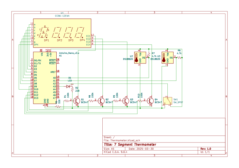
You can follow this diagram to replicate the circuit I used, this should let the code function with no modification
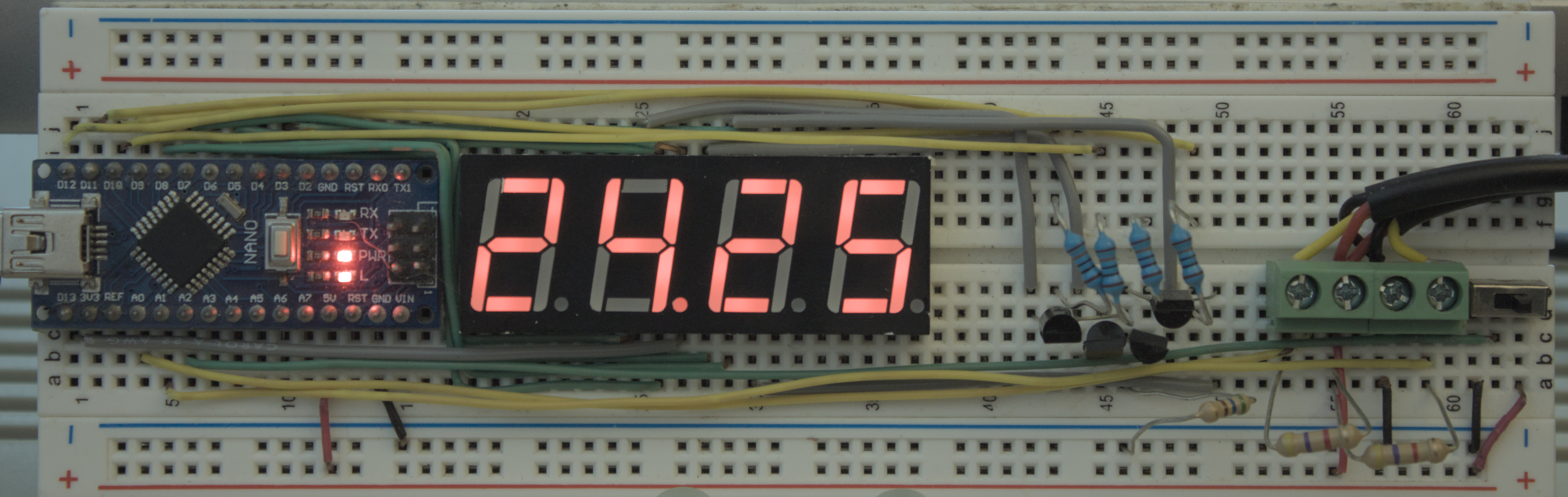
Here is the version that I built on a prototyping breadboard, it's a bit of a sloppy prototype but it works
At some point a run of PCBs may be manufactured
email: astew2693@gmail.com
see LICENSE for details
| Qty | Value | Footprint | References |
|---|---|---|---|
| 4 | 100k | Resistor_THT:R_Axial_DIN0204_L3.6mm_D1.6mm_P5.08mm_Horizontal | R4, R8, R9, R10 |
| 4 | BC547 | Package_TO_SOT_THT:TO-92_Inline | Q1, Q2, Q3, Q4 |
| 2 | 4.7k | Resistor_THT:R_Axial_DIN0204_L3.6mm_D1.6mm_P5.08mm_Horizontal | R6, R7 |
| 2 | DS18B20 | Package_TO_SOT_THT:TO-92_Inline | U2, U3 |
| 1 | 220 | Resistor_THT:R_Axial_DIN0204_L3.6mm_D1.6mm_P5.08mm_Horizontal | R2 |
| 1 | 550 | Resistor_THT:R_Axial_DIN0204_L3.6mm_D1.6mm_P5.08mm_Horizontal | R5 |
| 1 | Arduino_Nano_v2.x | Module:Arduino_Nano | Arduino Nano |
| 1 | CC56-12EWA | Display_7Segment:CA56-12EWA | U1 |
| 1 | LED | LED_THT:LED_D5.0mm | D1 |
| 1 | SW_SPDT | Button_Switch_THT:SW_CK_JS202011CQN_DPDT_Straight | SW1 |

adbik4/DL-FinalProject
The design and implementation of a measurement and data logging system based on ATmega328pb microcontroller. The system is intended for measuring temperature and pressure using dedicated digital sensors: DS18B20 and…


AK-Homberger/NMEA2000WifiGateway-with-ESP32
This repository shows how to build a NMEA2000 WiFi Gateway with voltage and temperature alarms.

nodep/NovaBox
Circuit and PCB design of simple Bluetooth stereo receiver and amplifier

anshukumar146/GitHub
A compact, self-contained development board for the 8051 microcontroller family (AT89x51xxP), designed in KiCad — built to run 8051 firmware on the bench with nothing more than a barrel-jack power supply and a…

deveth0/esphome-brunnen
esphome project to monitor waterlevel and temperature of a well or cistern

xrayer2000/MashMachine
My own built brewing system for making wonderful beer at home
It measures 55.4 × 52.8 mm and has 2 copper layers, 1.6 mm thick.
18 parts, built around the DS18B20, CC56-12EWA and BC547. The full list of its parts is on this page, with links to each part's symbol and footprint where PCBKit's library has them.
From the enragedcanadiangoose/7-Segment-Thermometer repository on GitHub, at the commit this page was made from: the board is schematic/Thermometer.kicad_pcb and its schematic schematic/Thermometer.kicad_sch. PCBKit opens the board in the browser, with nothing to install.
Its repository publishes it under the GPL-3.0 licence: you may reuse it on that licence's terms (keep the author's notice, and for a copyleft licence share your changes alike).