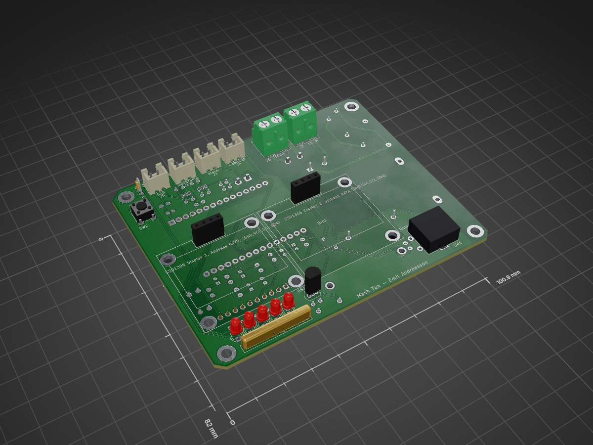
2 layers100.9 × 82 mm
MashMachine V2.1 PT100
xrayer2000/MashMachine
My own built brewing system for making wonderful beer at home
51 parts1
 xrayer2000/MashMachine1
My own built brewing system for making wonderful beer at home
MashMachine V2.0 is an open-source printed circuit board by xrayer2000, from the xrayer2000/MashMachine repository on GitHub. It is a 2-layer board of 100.9 × 82 mm with 62 parts on 57 nets, routed with 555 tracks and 17 vias.
It is built around the HLK-5M03, ADS1115IDGS and DS18B20, with the BC547, 14D471K and MF72 5D9-3.5 among its other parts. Its parts include 17 capacitors, 11 resistors, 6 connectors, 5 ICs and 3 diodes. It belongs with the ESP32 boards of this library.


An automated homebrewing system developed around a modified Vevor mash tun, an ESP32-based controller and custom temperature regulation.
This project has been a great journey for me to learn even more about the subjects covered in the MPSYS (Systems, Control and Mechatronics) programme at Chalmers University of Technology.
I have specifically applied knowledge from two courses:
The mash tun has served as a physical test platform for applying system identification and control theory to a real-world thermal system.
The starting point for this project was a relatively basic mash tun from Vevor, which only supported simple heating through its original controller.
I decided to modify the vessel and develop a custom control system to improve temperature regulation and automate the brewing process.
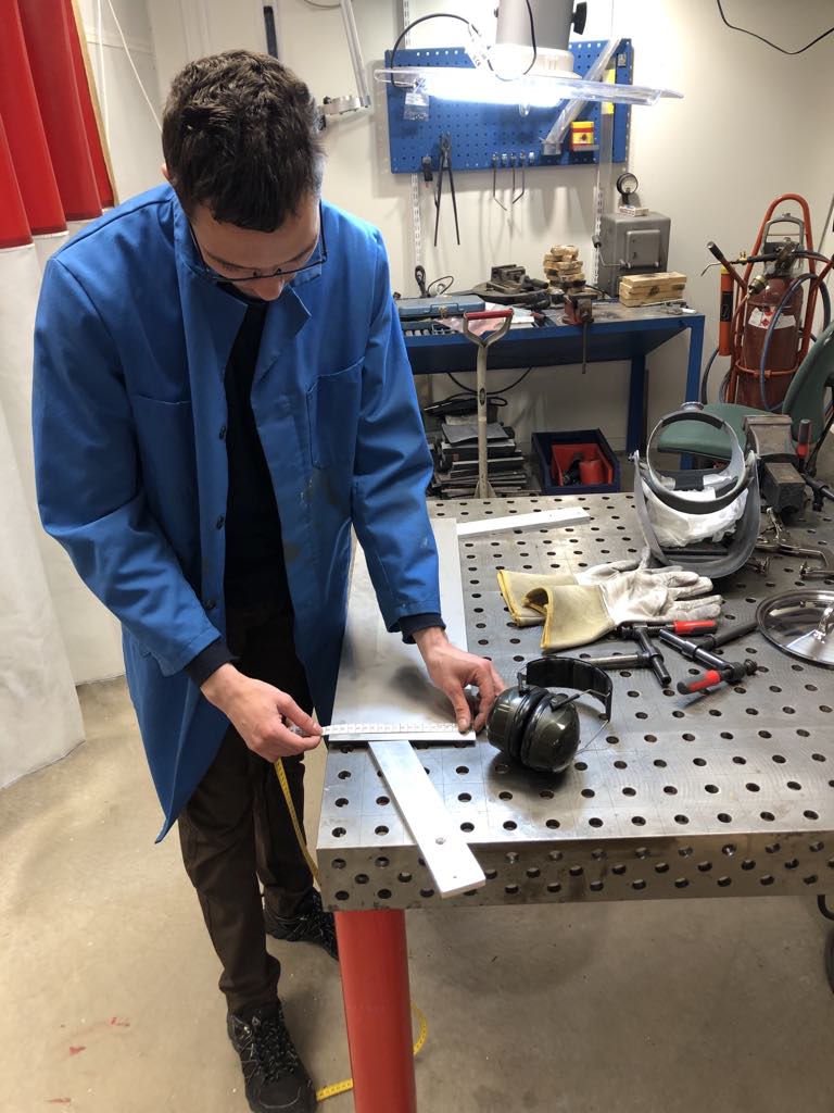
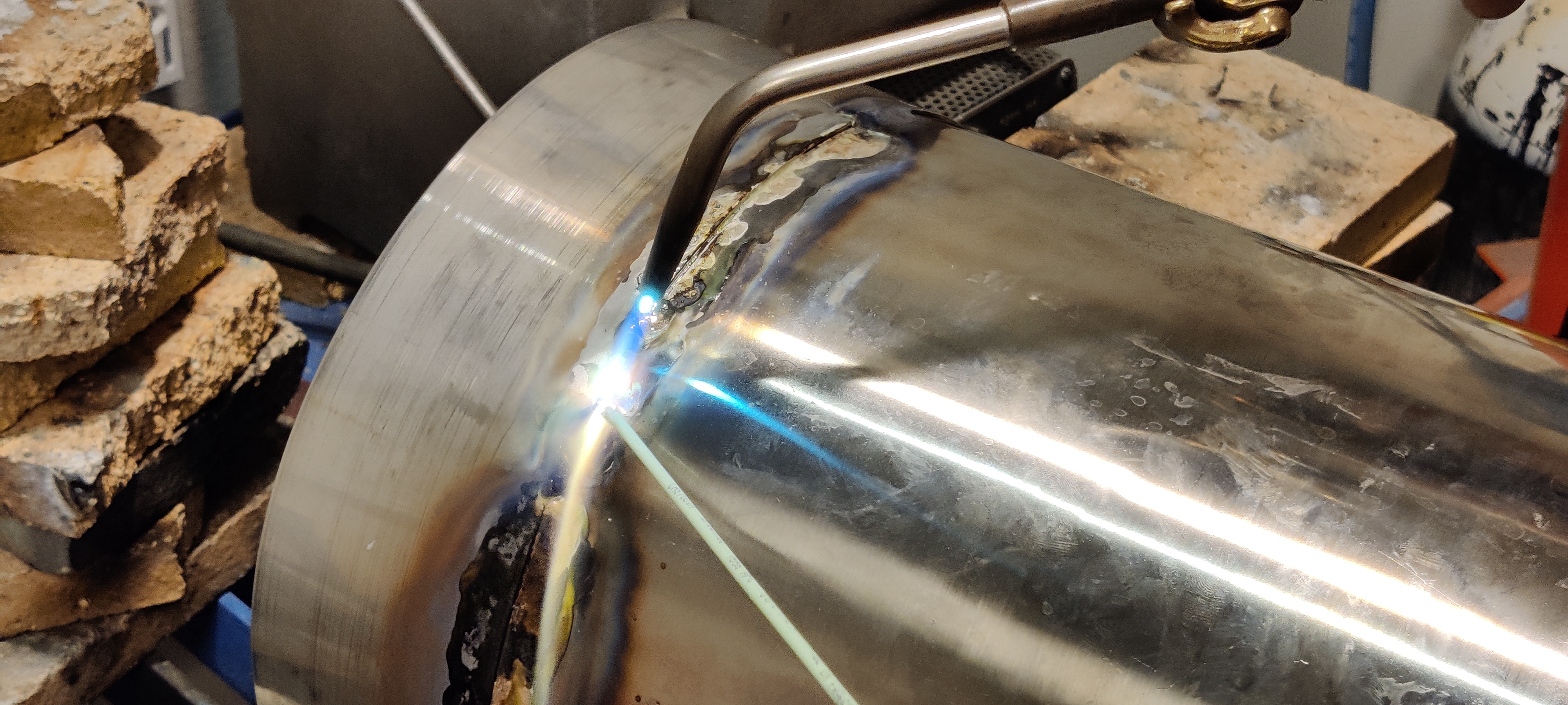
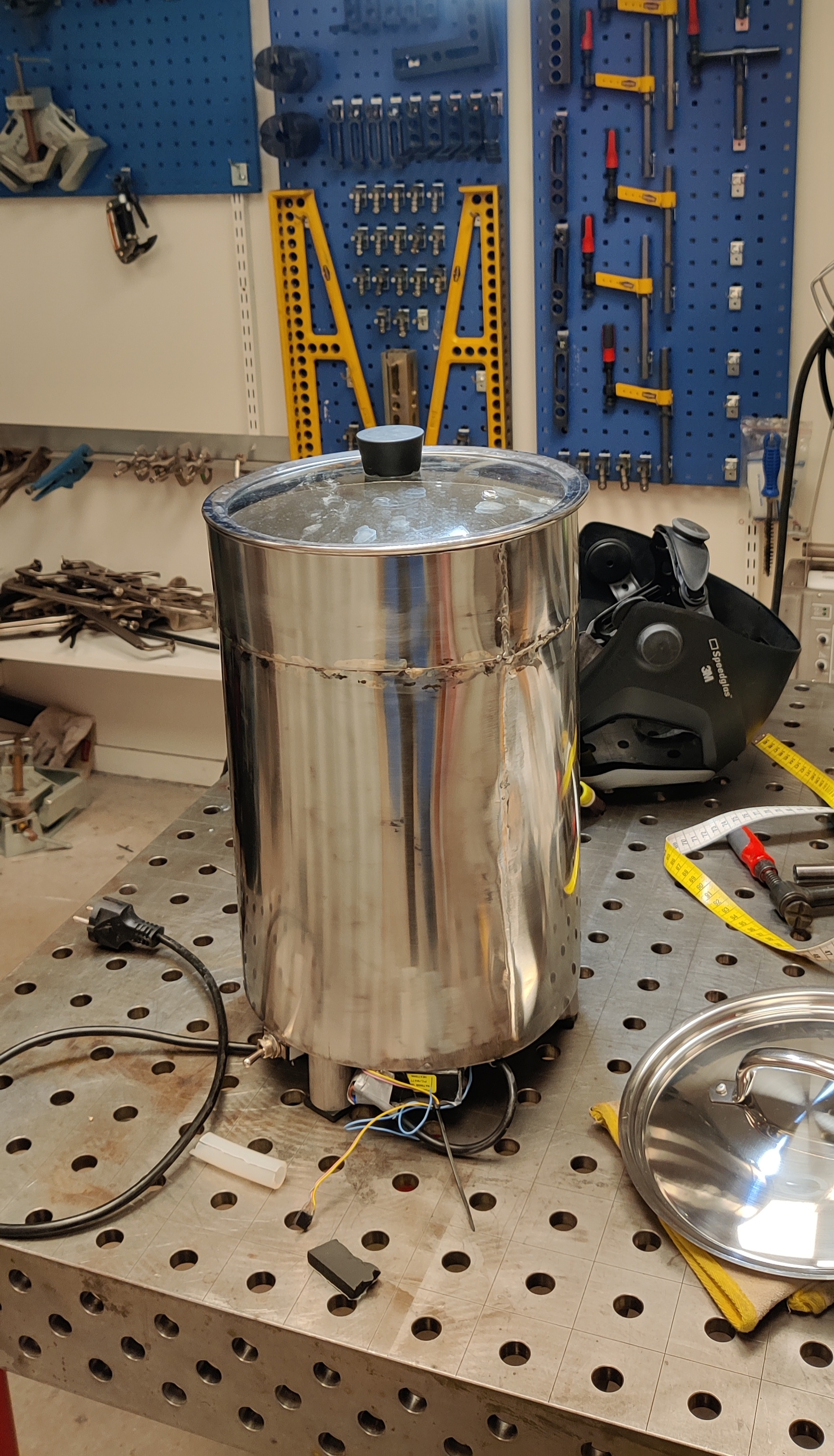
The mechanical work involved modifying the stainless-steel vessel, welding components, installing the necessary hardware and constructing an insulated enclosure.
The following photographs document parts of the fabrication process, including the initial measurements, stainless-steel vessel and welding.
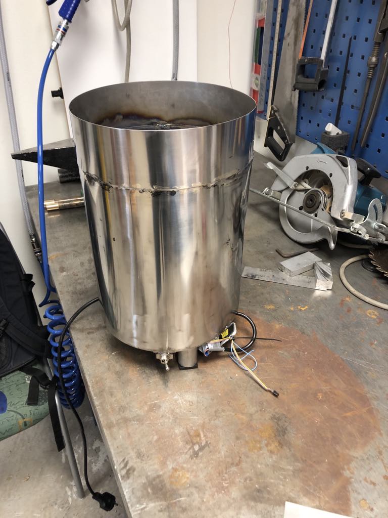
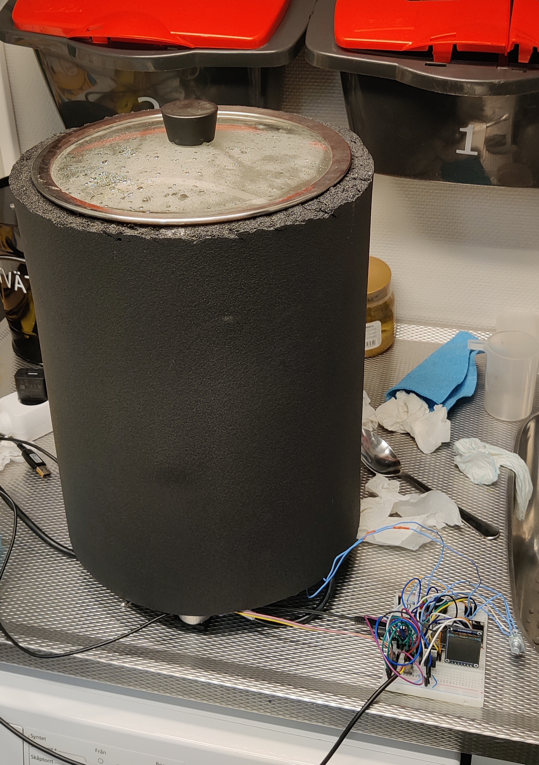
The finished vessel has an insulated exterior to reduce heat losses and improve thermal efficiency.
https://github.com/user-attachments/assets/f25a4e15-6e44-4505-bbf4-2bfe34d7de5a
https://github.com/user-attachments/assets/1c13a10b-537a-4cbe-8e05-aff711293a5b
The original controller was removed and replaced with a custom-built ESP32-based control system.
Several hardware modifications were made:
The circulation system improves temperature uniformity and makes the system more suitable for model-based control.
The original system exhibited temperature overshoot of around 2°C. With the new controller, temperature regulation is significantly improved, with essentially no observable overshoot under normal operating conditions.
Additional functionality includes:
In the System Identification course, I used the mash tun to collect both estimation and validation data.
Using the System Identification Toolbox in MATLAB, I derived state-space models for three different operating points:
All system matrices were computed in MATLAB and then implemented directly on the ESP32. The computational work was therefore performed offline rather than on the microcontroller.
Once the state-space models had been obtained, I used the concepts from Design of Linear Control Systems to design controllers based on the identified models.
I initially implemented a state-feedback LQR controller and later extended it to an LQG controller by adding a Kalman filter for state estimation.
LQG requires an explicit state-space representation of the system dynamics. Unlike conventional PID control, which operates on the control error, LQG uses a model to estimate internal system states and calculate the control input.
However, the LQG controller turned out to be somewhat excessive for this application, since the system exhibits slow and stable thermal dynamics. A well-tuned PID controller would likely have been sufficient.
The system initially used an NTC thermistor. This approach was eventually abandoned due to calibration difficulties and unreliable measurements.
The NTC sensor is strongly nonlinear and requires reliable calibration points consisting of temperature and resistance.
In practice, this introduced several problems:
These issues resulted in deviations between measured and actual temperatures.
The NTC was replaced with a PT100 resistance temperature detector (RTD).
The main reasons were:
This change significantly improved the quality of the temperature measurements, which is particularly important for system identification and state estimation.
The system is integrated with Home Assistant for monitoring and interaction.
A local Linux machine acts as a small server, running Home Assistant in a Docker container. The same setup also runs supporting services such as InfluxDB and Grafana.
Communication between the ESP32 and Home Assistant is handled using MQTT.
This setup enables:
The integration is useful not only for convenience, but also for collecting experimental data and observing controller performance over time.
The mash tun exhibits slow dynamics and significant thermal inertia.
Measurements are also affected by noise, making aggressive control unsuitable.
As a result, stability and consistent temperature regulation are more important than fast response.
The main difficulty in this project was not the controller design itself.
The most challenging aspects were:
The project has provided an opportunity to apply theoretical concepts from system identification and control engineering to a practical application.
A special thanks to my dad for giving me the opportunity to carry out the welding work at his workplace, MTA Sahlgrenska. His help made the fabrication of the stainless-steel mash tun possible, and I really appreciate his support throughout the project.
| Qty | Value | Footprint | References |
|---|---|---|---|
| 7 | 100n | Capacitor_THT:C_Disc_D3.0mm_W1.6mm_P2.50mm | C2, C6, C8, C9, C11, C13, C17 |
| 4 | MountingHole | MountingHole:MountingHole_3.2mm_M3_DIN965_Pad | H1, H2, H3, H4 |
| 3 | 4.7k | Resistor_THT:R_Axial_DIN0204_L3.6mm_D1.6mm_P2.54mm_Vertical | R4, R5, R6 |
| 2 | 10k | Resistor_THT:R_Axial_DIN0204_L3.6mm_D1.6mm_P2.54mm_Vertical | R9, R11 |
| 2 | 10n | Capacitor_THT:C_Disc_D3.0mm_W1.6mm_P2.50mm | C3, C4 |
| 2 | 1k | Resistor_THT:R_Axial_DIN0204_L3.6mm_D1.6mm_P2.54mm_Vertical | R8, R10 |
| 2 | 2.2u | Capacitor_THT:CP_Radial_D4.0mm_P2.00mm | C1, C10 |
| 2 | 22u | Capacitor_THT:CP_Radial_D4.0mm_P2.00mm | C12, C16 |
| 2 | BC547 | Package_TO_SOT_THT:TO-92_Inline | Q1, Q2 |
| 1 | 0 | Resistor_THT:R_Axial_DIN0204_L3.6mm_D1.6mm_P1.90mm_Vertical | R7 |
| 1 | 100k | Resistor_THT:R_Axial_DIN0207_L6.3mm_D2.5mm_P7.62mm_Horizontal | R1 |
| 1 | 100nf X2 275 VAC MKP | Capacitor_THT:C_Rect_L16.5mm_W6.0mm_P15.00mm_MKT | C14 |
| 1 | 10k | Resistor_THT:R_Axial_DIN0207_L6.3mm_D2.5mm_P7.62mm_Horizontal | R3 |
| 1 | 10u | Capacitor_THT:CP_Radial_D4.0mm_P2.00mm | C15 |
| 1 | 14D471K | Varistor:RV_Disc_D15.5mm_W4.5mm_P7.5mm | RV1 |
| 1 | 1k | Resistor_THT:R_Array_SIP9 | RN1 |
| 1 | 1k | Resistor_THT:R_Axial_DIN0207_L6.3mm_D2.5mm_P7.62mm_Horizontal | R2 |
| 1 | 1u | Capacitor_THT:CP_Radial_D4.0mm_P2.00mm | C18 |
| 1 | 4.7u | Capacitor_THT:CP_Radial_D4.0mm_P2.00mm | C7 |
| 1 | 470 Ω @ 100 MHz | Capacitor_SMD:C_0805_2012Metric_Pad1.18x1.45mm_HandSolder | FB1 |
| 1 | ADS1115IDGS | Connector_PinSocket_2.54mm:PinSocket_1x10_P2.54mm_Vertical | U2 |
| 1 | Alarm | Connector_JST:JST_XH_B2B-XH-AM_1x02_P2.50mm_Vertical | J3 |
| 1 | DC | LED_THT:LED_D3.0mm | DC1 |
| 1 | DS18B20 | Package_TO_SOT_THT:TO-92L_Inline | Air_temp1 |
| 1 | ESP32-DEVKIT-V1 | ESP32_DEVKIT_V1:ESP32_DEVKIT_V1 | U4 |
| 1 | HLK-5M03 | Converter_ACDC:Converter_ACDC_Hi-Link_HLK-5Mxx | PS1 |
| 1 | L1, N | TerminalBlock_RND:TerminalBlock_RND_205-00287_1x02_P5.08mm_Horizontal | J2 |
| 1 | MF72-5D-9 | Varistor:RV_Disc_D9mm_W5.2mm_P5mm | TH1 |
| 1 | Mqtt | LED_THT:LED_D3.0mm | LED2 |
| 1 | On | LED_THT:LED_D3.0mm | OnOff1 |
| 1 | PPTC 1.1A | Fuse:Fuse_BelFuse_0ZRE0016FF_L9.9mm_W3.8mm | F2 |
| 1 | Rotary_Encoder_Switch | Rotary_Encoder:RotaryEncoder_Alps_EC11E-Switch_Vertical_H20mm | SW1 |
| 1 | SSD1306 Display 1, Addesss 0x78, (GND,VCC,SCL,SDA) | SSD1306:ssd1306_1.3'' | Brd1 |
| 1 | SSD1306 Display 2, address 0x7A (GND,VCC,SCL,SDA) | SSD1306:ssd1306_1.3'' | Brd2 |
| 1 | SSR | Connector_JST:JST_XH_B2B-XH-AM_1x02_P2.50mm_Vertical | J5 |
| 1 | SSR-41FDA | OptoDevice:Finder_34.81 | U5 |
| 1 | SW_Push | Button_Switch_THT:SW_PUSH_6mm | SW2 |
| 1 | T250mA | Fuse_Holders_and_Fuses:Fuseholder5x20_horiz_SemiClosed_Casing10x25mm | F1 |
| 1 | TPS7A0328PDBVR | Package_TO_SOT_SMD:SOT-23-5 | U1 |
| 1 | Water | LED_THT:LED_D3.0mm | LED3 |
| 1 | Wifi | LED_THT:LED_D3.0mm | LED1 |
| 1 | mashTemp | Connector_JST:JST_XH_B2B-XH-AM_1x02_P2.50mm_Vertical | J1 |
| 1 | pump | TerminalBlock_RND:TerminalBlock_RND_205-00287_1x02_P5.08mm_Horizontal | J6 |
| 1 | waterDet | Connector_JST:JST_XH_B2B-XH-AM_1x02_P2.50mm_Vertical | J4 |
| 1 | ~ | AllprojectsFootprint:AlarmModule | U3 |
xrayer2000/MashMachine
My own built brewing system for making wonderful beer at home

xrayer2000/MashMachine
My own built brewing system for making wonderful beer at home

xrayer2000/MashMachine
My own built brewing system for making wonderful beer at home


alejomancinelli/FCEIA_ProyectoFinal
Proyecto Final de Ing. Electrónica: Sistema de monitoreo de red eléctrica doméstica y/o industrial


Qeteshpony/MainsFrequencyMonitor
Single board solution to power an ESP32 and use it to measure the mains frequency through an optoisolator

pablozg/freeds
Derivador de energía solar excedente creado por Pablo Zerón, Diseño PCB por Amcalo, Tester original por Aeizoon, Wiki por Zoilo Mora


enriquewph/potenciatp4
Fuente Conmutada 50W 24V 2.4A de la cátedra Electrónica de Potencia - Grupo 3 - 5R2
It measures 100.9 × 82 mm and has 2 copper layers, 1.6 mm thick.
62 parts, built around the HLK-5M03, ADS1115IDGS, DS18B20 and BC547. The full list of its parts is on this page, with links to each part's symbol and footprint where PCBKit's library has them.
From the xrayer2000/MashMachine repository on GitHub, at the commit this page was made from: the board is Kicad/MashMachine V2.0/MashMachine V2.0.kicad_pcb and its schematic Kicad/LauteringTun/LauteringTun.kicad_sch. PCBKit opens the board in the browser, with nothing to install.
Its repository states no licence, so its author keeps all rights: ask xrayer2000 before reusing the design.