2 layers20 × 10.5 mm
Attentiolight-1-1ledmodule1
engemil/attentiolight-1-hardware
AttentioLight-1 Hardware
7 parts1CERN-OHL-P-2.0

 engemil/attentiolight-1-hardware1
AttentioLight-1 Hardware
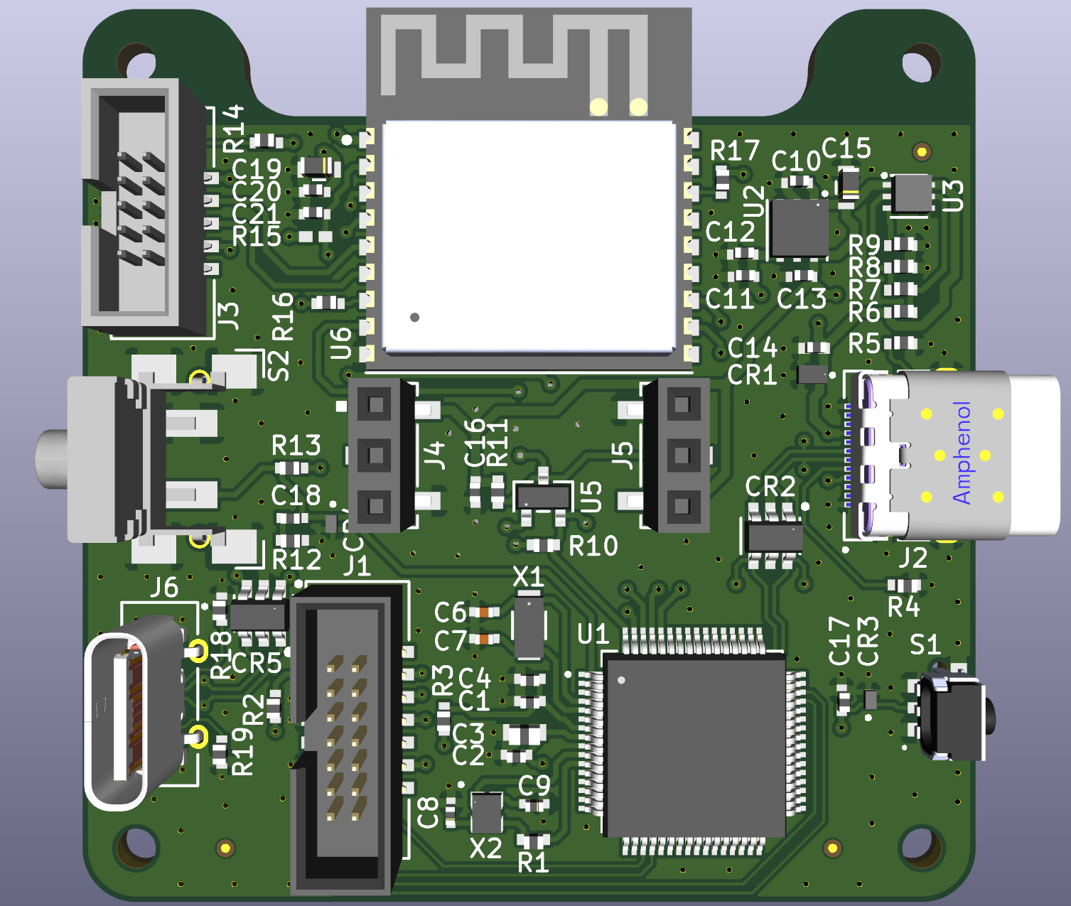
Attentiolight-1-mainboard1 is an open-source printed circuit board by engemil, from the engemil/attentiolight-1-hardware repository on GitHub, published under the CERN-OHL-P-2.0 licence. It is a 4-layer board of 50 × 50 mm with 80 parts on 117 nets, routed with 743 tracks and 261 vias.
It is built around the STM32C071RBT6, ESP32-C3-WROOM-02-N4 and BSS138, with the LD39100PU33R, ESD321DPYR and NPTC031KFXC-RC among its other parts. Its parts include 20 capacitors, 19 resistors, 6 connectors, 5 ICs and 2 switches. It belongs with the ESP32, STM32 and RISC-V boards of this library.


The AttentioLight-1 is a personal light indicator. A status indicator in real-life, showing your availability or use it as a pomodoro focus timer, and more!
Designed to integrate with any device over USB-C, wirelessly, bluetooth, or WiFi. Connect it to your computer, smartphone, or use it as a stand-alone device.
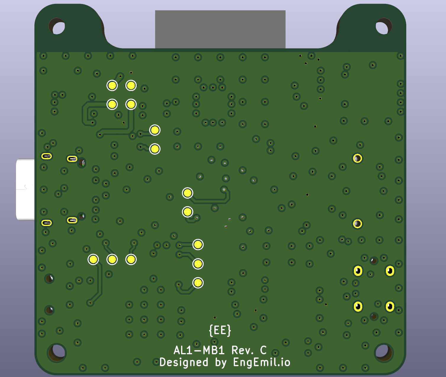
Mainboard-1 Rev. C
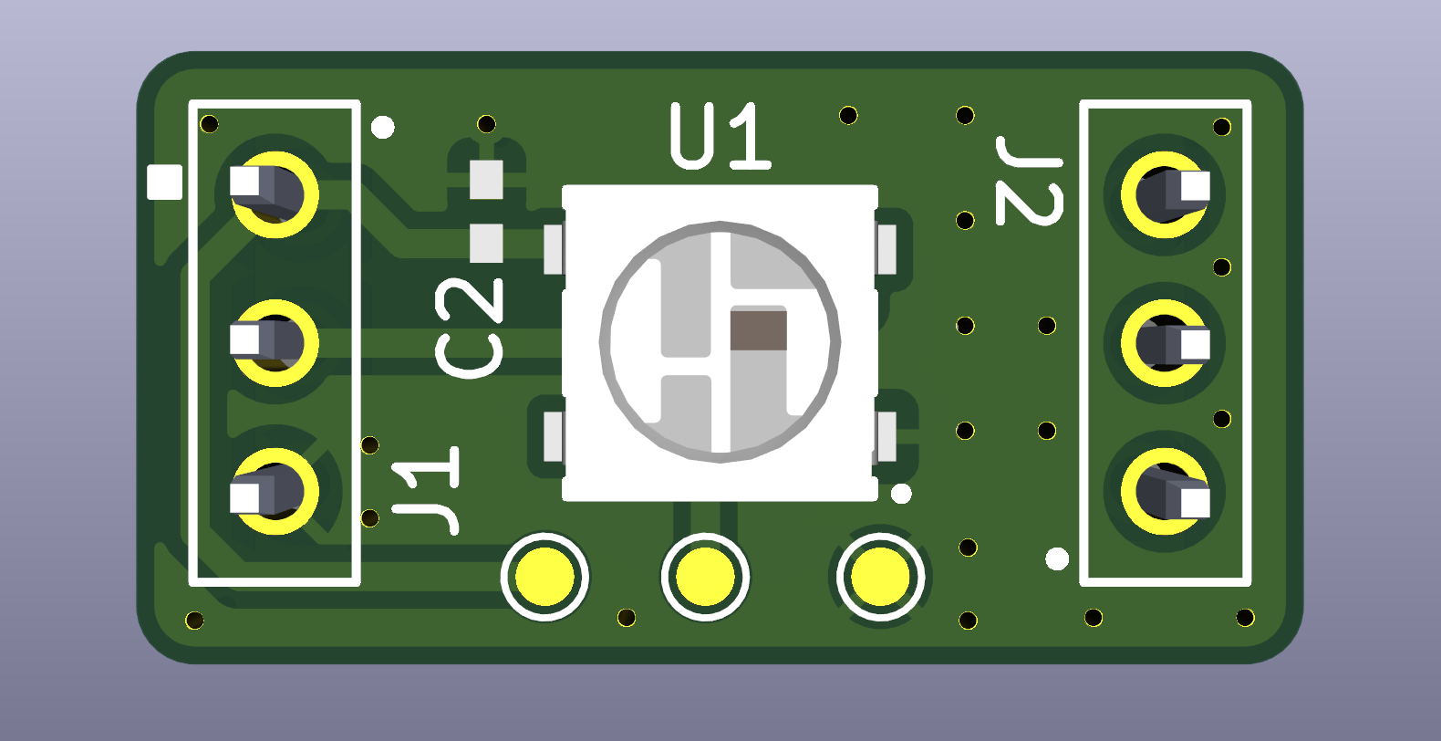
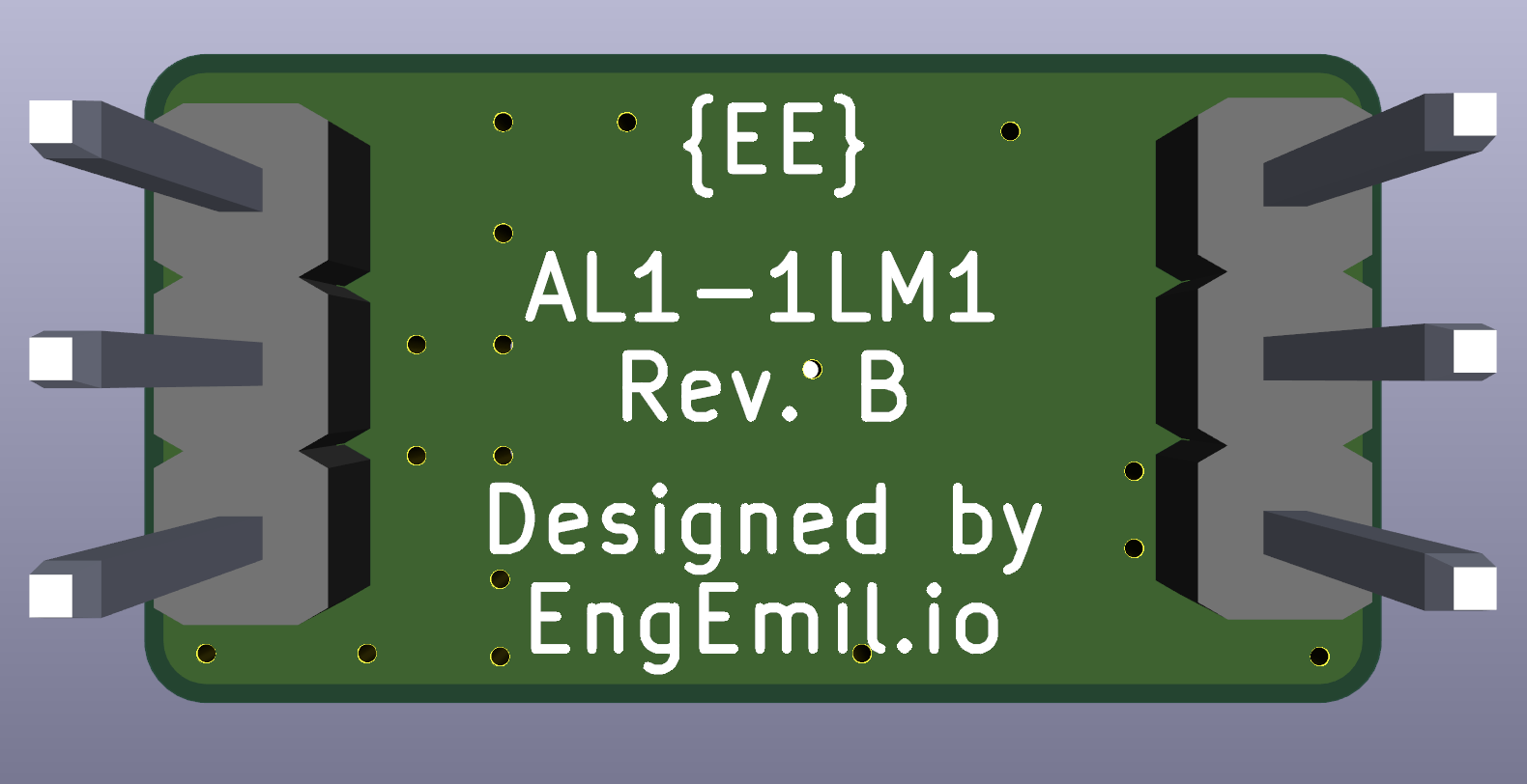
1 LED Module-1 Rev. B
attentiolight-1-1ledmodule1 - KiCAD project files for the AttentioLight-1 1LEDModule1.attentiolight-1-mainboard1 - KiCAD project files for the AttentioLight-1 Mainboard1.docs - Additional files for documentation/readme.manufacturing - Manufacturing files for producing the PCBs (such as Gerber-files), component placement file(s), and BOM-files.pdfs - PDF files for the schematic and PCB Design.Design rules used: https://jlcpcb.com/capabilities/pcb-capabilities
| Qty | Value | Footprint | References |
|---|---|---|---|
| 14 | TestPoint | attentiolight-1-mainboard1:TestPoint_Pad_Back_D1.0mm | TP1, TP2, TP3, TP4, TP5, TP6, TP7, TP8, TP9, TP10, TP11, TP12, TP13, TP14 |
| 8 | 100nF | attentiolight-1-mainboard1:YAG_CC0402_YAG | C1, C2, C10, C12, C16, C17, C18, C20 |
| 5 | 10k | attentiolight-1-mainboard1:RESC1005X40N | R10, R11, R15, R16, R17 |
| 5 | 5.1k | attentiolight-1-mainboard1:RESC1005X40N | R4, R5, R13, R18, R19 |
| 4 | 0Ohms | attentiolight-1-mainboard1:RESC1005X40N | R1, R2, R3, R14 |
| 4 | 1uF | attentiolight-1-mainboard1:YAG_CC0402_YAG | C4, C11, C13, C21 |
| 4 | MountingHole | MountingHole:MountingHole_2.2mm_M2 | H1, H2, H3, H4 |
| 3 | Fiducial | Fiducial:Fiducial_0.5mm_Mask1mm | FID1, FID2, FID3 |
| 2 | 10uF | attentiolight-1-mainboard1:CAP_1608_TDK | C15, C19 |
| 2 | 6pF | attentiolight-1-mainboard1:G-155_MUR | C8, C9 |
| 2 | 7.5pF | attentiolight-1-mainboard1:G-155_MUR | C6, C7 |
| 2 | ESD321DPYR | attentiolight-1-mainboard1:DPY2_TEX_v2 | CR3, CR4 |
| 2 | NPTC031KFXC-RC | attentiolight-1-mainboard1:CONN03_NPTC031KFXC-RC_SUL | J4, J5 |
| 2 | USBLC6-2SC6 | attentiolight-1-mainboard1:SOT23-6L_STM | CR2, CR5 |
| 1 | 100Ohms | attentiolight-1-mainboard1:RESC1005X40N | R12 |
| 1 | 100pF | attentiolight-1-mainboard1:CAP_CC0402_YAG | C14 |
| 1 | 137k | attentiolight-1-mainboard1:RESC1005X40N | R8 |
| 1 | 1571300-2 | attentiolight-1-mainboard1:CUSTOM_SW_FP_1571300-2 | S2 |
| 1 | 32.768KHz | attentiolight-1-mainboard1:XTAL_MU00525_NDK | X1 |
| 1 | 3220-10-0300-00 | attentiolight-1-mainboard1:CONN_3220-10-0300-00_CNC | J3 |
| 1 | 3220-14-0300-00 | attentiolight-1-mainboard1:CONN_3220-14-0300-00_CNC | J1 |
| 1 | 4.7uF | attentiolight-1-mainboard1:YAG_CC0603_YAG | C3 |
| 1 | 44.2k | attentiolight-1-mainboard1:RESC1005X40N | R9 |
| 1 | 470k | attentiolight-1-mainboard1:RESC1005X40N | R6 |
| 1 | 48MHz | attentiolight-1-mainboard1:NX2016SA-48M_NDK | X2 |
| 1 | 68.1k | attentiolight-1-mainboard1:RESC1005X40N | R7 |
| 1 | BSS138 | attentiolight-1-mainboard1:SOT-23_3L_ONS | U5 |
| 1 | ESDA25P35-1U1M | attentiolight-1-mainboard1:QFN1610_STM | CR1 |
| 1 | ESP32-C3-WROOM-02-N4 | attentiolight-1-mainboard1:IC18_ESP32-C3-WROOM-02-N4_EXP | U6 |
| 1 | LD39100PU33R | attentiolight-1-mainboard1:DFN_00PU33R_STM-L | U2 |
| 1 | PTS845VN20PSMTR4_LFS | attentiolight-1-mainboard1:PTS845VN20PSMTR4LFS | S1 |
| 1 | STM32C071RBT6 | attentiolight-1-mainboard1:LQFP-64_STM | U1 |
| 1 | TPS25961DRVR | attentiolight-1-mainboard1:DRV0006A-IPC_A | U3 |
| 1 | USB-C | attentiolight-1-mainboard1:12401826_AMP | J2 |
| 1 | USB4120-03-C | attentiolight-1-mainboard1:USB4120-03-C_GCT | J6 |
engemil/attentiolight-1-hardware
AttentioLight-1 Hardware

WidRojas/PCB-Hardware-Projects
Repo containing all PCB files alongside short project descriptions


Andresse2020/NovaDrone-Hardware
Complete electronic system design for a high-performance quadcopter drone, developed entirely from scratch. Includes power distribution, motor control, flight stabilization, sensor integration, and communication…


It measures 50 × 50 mm and has 4 copper layers, 1.58 mm thick.
80 parts, built around the STM32C071RBT6, ESP32-C3-WROOM-02-N4, BSS138 and LD39100PU33R. The full list of its parts is on this page, with links to each part's symbol and footprint where PCBKit's library has them.
From the engemil/attentiolight-1-hardware repository on GitHub, at the commit this page was made from: the board is attentiolight-1-mainboard1/attentiolight-1-mainboard1.kicad_pcb and its schematic attentiolight-1-1ledmodule1/attentiolight-1-1ledmodule1.kicad_sch. PCBKit opens the board in the browser, with nothing to install.
Its repository publishes it under the CERN-OHL-P-2.0 licence: you may reuse it on that licence's terms (keep the author's notice, and for a copyleft licence share your changes alike).