
2 layers33.7 × 97.8 mm
HAN ESP TSS721
UtilitechAS/amsreader-firmware
ESP8266 and ESP32 compatible firmware to read, interpret and publish data to MQTT from smart electrical meters, both DLMS and DSMR is supported
29 parts470

 emtpb/pmi-hw-bob2
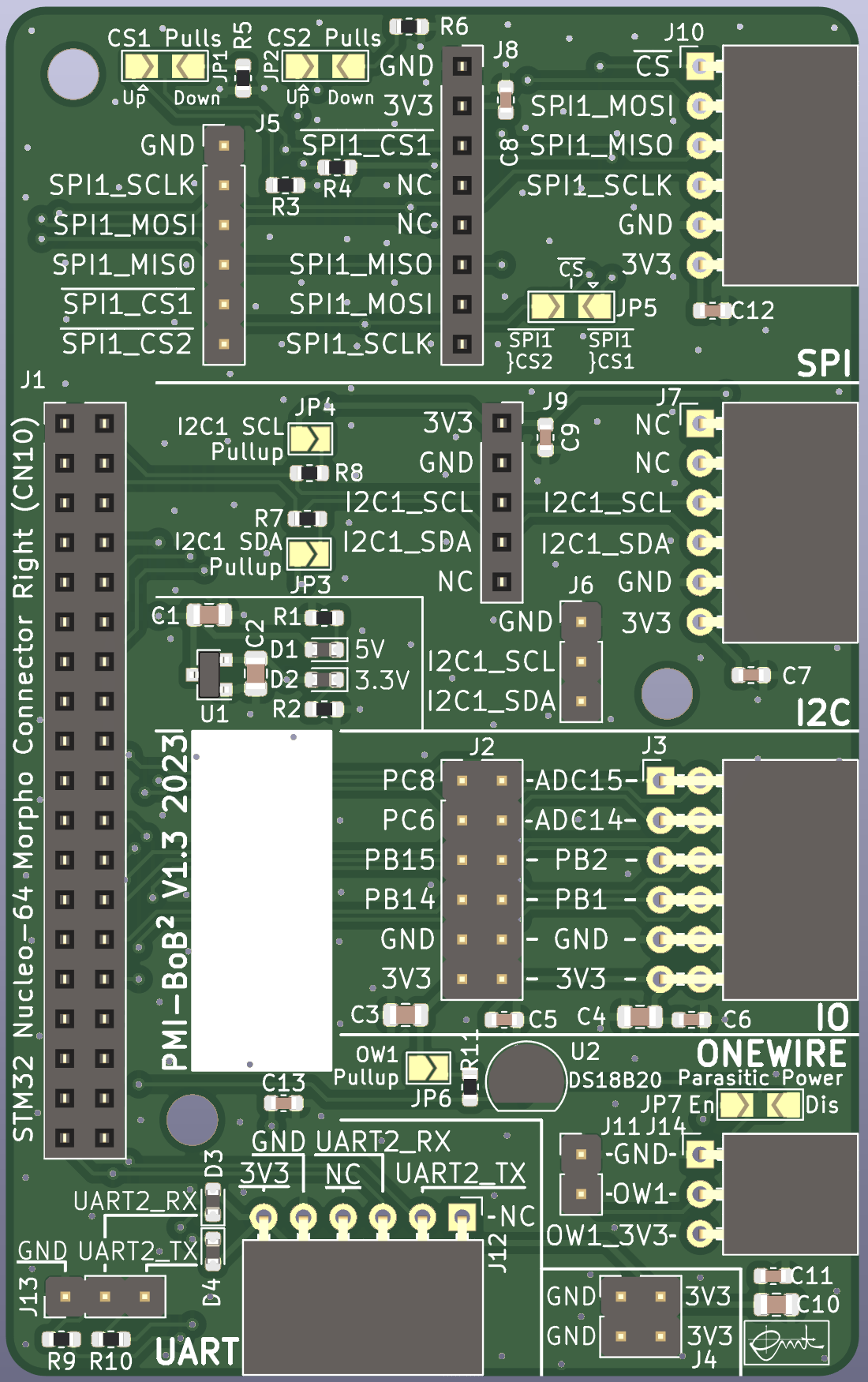
This pcb is designed for the course PMI (Practical course Microcontroller and Interface electronics) as a breakout board for right morpho connector (CN10) of STM32 Nucleo-64 boards.
Pmi hw bob2 is an open-source printed circuit board by emtpb, from the emtpb/pmi-hw-bob2 repository on GitHub. It is a 2-layer board of 54.6 × 87.6 mm with 58 parts on 57 nets, routed with 369 tracks and 211 vias.
It is built around the DS18B20. Its parts include 14 connectors, 13 capacitors, 11 resistors, 4 diodes and 2 ICs. It belongs with the sensors and measurement and interfaces and adapters boards of this library.
This pcb is designed for the course PMI (Practical course Microcontroller and Interface electronics) as a breakout board for right morpho connector (CN10) of STM32 Nucleo-64 boards. It distributes several signals and bus systems like SPI, I²C, 1-wire, UART and GPIOs. Signal distribution is achieved by pin sockets and headers. The headers can be used to tap signal for anaysis with oscilloscopes or logic analyzers. It also features a 3.3V LDO voltage regulator for power supply and an on board 1-wire DS18B20+ temperature sensor. SPI Chip selects, I²C pull-up resistors and 1-wire parasitic power supply can be enabled over solder bridges.
There are interfaces for GY-291 (ADXL345 accelerometer) and GY-271 (HMC5883L magnet sensor) as well as for our PMI-ALICE and PMI-CARLOS breakout boards. Vertical pin sockets are compatible with Digilents Pmod interfaces.
An interactive html BOM page with pcb layout and material placement can be found here.
| Qty | Value | Footprint | References |
|---|---|---|---|
| 8 | 100nF | Capacitor_SMD:C_0603_1608Metric | C5, C6, C7, C8, C9, C11, C12, C13 |
| 5 | 1µF | Capacitor_SMD:C_0805_2012Metric | C1, C2, C3, C4, C10 |
| 4 | 10k | Resistor_SMD:R_0603_1608Metric | R3, R4, R5, R6 |
| 3 | 2.2k | Resistor_SMD:R_0603_1608Metric | R1, R7, R8 |
| 3 | MountingHole | MountingHole:MountingHole_3.2mm_M3 | H1, H2, H3 |
| 1 | 330 | Resistor_SMD:R_0603_1608Metric | R10 |
| 1 | 3V3 PWR | Diode_SMD:D_0603_1608Metric | D2 |
| 1 | 4.7k | Resistor_SMD:R_0603_1608Metric | R11 |
| 1 | 560 | Resistor_SMD:R_0603_1608Metric | R9 |
| 1 | 5V PWR | Diode_SMD:D_0603_1608Metric | D1 |
| 1 | 680 | Resistor_SMD:R_0603_1608Metric | R2 |
| 1 | Bob-DS18B20 | Bobs-emt:Bob_DS18B20_Host | J14 |
| 1 | Bob-GY271 | Connector_PinSocket_2.54mm:PinSocket_1x05_P2.54mm_Vertical | J9 |
| 1 | Bob_GY291_ADXL345 | Connector_PinSocket_2.54mm:PinSocket_1x08_P2.54mm_Vertical | J8 |
| 1 | Bob_St_N64_Morpho_Right | Bobs-emt:ST_N64_Morpho_Right-emt | J1 |
| 1 | CS1Pulls | Jumper:SolderJumper-3_P2.0mm_Open_TrianglePad1.0x1.5mm | JP1 |
| 1 | CS2Pulls | Jumper:SolderJumper-3_P2.0mm_Open_TrianglePad1.0x1.5mm | JP2 |
| 1 | DS18B20 | Package_TO_SOT_THT:TO-92_Inline | U2 |
| 1 | EMT-Logo | Symbol-emt:EMT-Logo_11.7x5.9mm_Silkscreen | H5 |
| 1 | EMT-Logo | Symbol-emt:EMT-Logo_5.1x2.5mm_Silkscreen | H4 |
| 1 | I2C1 | Connector_PinHeader_2.54mm:PinHeader_1x03_P2.54mm_Vertical | J6 |
| 1 | I2C1_PULLUP_SCL | Jumper:SolderJumper-2_P1.3mm_Open_TrianglePad1.0x1.5mm | JP4 |
| 1 | I2C1_PULLUP_SDA | Jumper:SolderJumper-2_P1.3mm_Open_TrianglePad1.0x1.5mm | JP3 |
| 1 | IO_SPI_CS_EN | Jumper:SolderJumper-3_P2.0mm_Open_TrianglePad1.0x1.5mm | JP5 |
| 1 | MCP1703AT-3302E_SOT23 | Package_TO_SOT_SMD:SOT-23 | U1 |
| 1 | OW1 | Connector_PinHeader_2.54mm:PinHeader_1x02_P2.54mm_Vertical | J11 |
| 1 | OW_PULLUP_EN | Jumper:SolderJumper-2_P1.3mm_Open_TrianglePad1.0x1.5mm | JP6 |
| 1 | PI_GPIO12 | Connector_PinHeader_2.54mm:PinHeader_2x06_P2.54mm_Vertical | J2 |
| 1 | PI_SPI1 | Pmod_Interface-emt:Pmod_Interface_Female6 | J10 |
| 1 | ParasiticPowerBridge | Jumper:SolderJumper-3_P2.0mm_Open_TrianglePad1.0x1.5mm_NumberLabels | JP7 |
| 1 | Pmod-I2C1 | Pmod_Interface-emt:Pmod_Interface_Female6 | J7 |
| 1 | Pmod-Interface-GPIO12 | Pmod_Interface-emt:Pmod_Interface_Female12 | J3 |
| 1 | Pmod-Interface-UART6 | Pmod_Interface-emt:Pmod_Interface_Female6 | J12 |
| 1 | RX_R | Diode_SMD:D_0603_1608Metric | D3 |
| 1 | SPI1 | Connector_PinHeader_2.54mm:PinHeader_1x06_P2.54mm_Vertical | J5 |
| 1 | TX_G | Diode_SMD:D_0603_1608Metric | D4 |
| 1 | UART2 | Connector_PinHeader_2.54mm:PinHeader_1x03_P2.54mm_Vertical | J13 |
| 1 | UPB-Logo | Symbol-emt:UPB-Logo_En_15.9X5.6mm | H6 |
| 1 | extPower | Connector_PinHeader_2.54mm:PinHeader_2x02_P2.54mm_Vertical | J4 |
| 1 | github.com-QR-Code | Symbol-emt:github-emtpb-pmi | H7 |
UtilitechAS/amsreader-firmware
ESP8266 and ESP32 compatible firmware to read, interpret and publish data to MQTT from smart electrical meters, both DLMS and DSMR is supported

pablozg/freeds
Derivador de energía solar excedente creado por Pablo Zerón, Diseño PCB por Amcalo, Tester original por Aeizoon, Wiki por Zoilo Mora

AK-Homberger/NMEA2000WifiGateway-with-ESP32
This repository shows how to build a NMEA2000 WiFi Gateway with voltage and temperature alarms.

fehlfarbe/arduino-motorfocus
Arduino motorfocus with moonlite protocol for telescopes


felixwittwer/homeassistant_automaic_greenhouse
A cool Project to make your greenhouse smart. What about automaic irrigation and collecting enviromental data right from your garden.

Neumi/fastLOGIC
An affordable Arduino-based board designed for straightforward (industrial) logic control, ideal for building small-scale automation and control solutions.
It measures 54.6 × 87.6 mm and has 2 copper layers, 1.6 mm thick.
58 parts, built around the DS18B20. The full list of its parts is on this page, with links to each part's symbol and footprint where PCBKit's library has them.
From the emtpb/pmi-hw-bob2 repository on GitHub, at the commit this page was made from: the board is pmi-hw-bob2.kicad_pcb and its schematic IO.kicad_sch. PCBKit opens the board in the browser, with nothing to install.
Its repository states no licence, so its author keeps all rights: ask emtpb before reusing the design.