4 layers50 × 40 mm
 Emele-Winner2/NODE1
A custom motion and environmental sensing device designed using KICAD
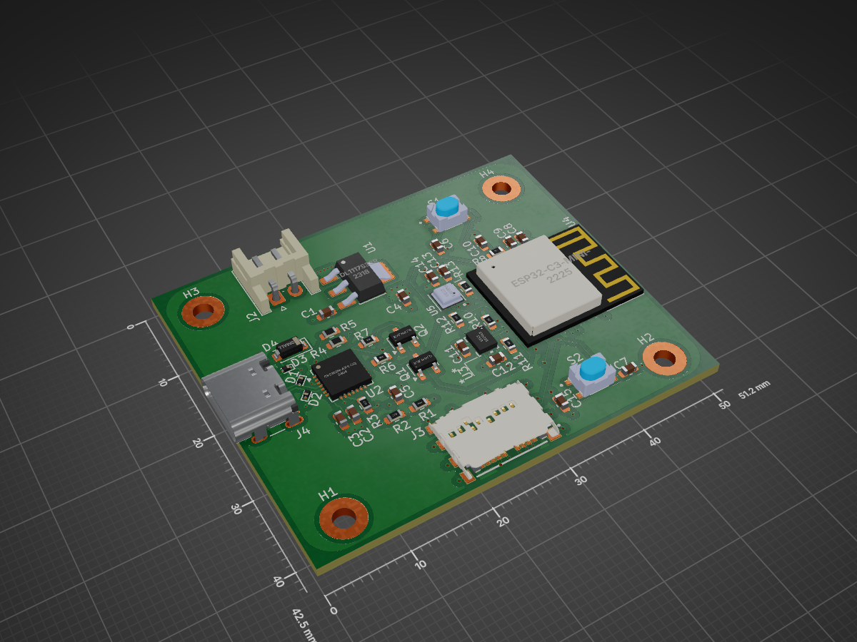
NODE IO BOARD is an open-source printed circuit board by Emele-Winner2, from the Emele-Winner2/NODE repository on GitHub. It is a 4-layer board of 51.2 × 42.5 mm with 48 parts on 73 nets, routed with 404 tracks and 120 vias.
It is built around the ESP32-C3-MINI-1-N4, BME688 and BMI323, with the LDL1117S33R, ESD9B5.0ST5G and SKRPABE010 among its other parts. Its parts include 15 capacitors, 13 resistors, 5 ICs, 4 diodes and 3 connectors. It belongs with the ESP32 and RISC-V boards of this library.


The NODE IO BOARD is an embedded hardware node featuring an ESP32-C3 microcontroller, onboard environmental and motion sensors, USB-C power/data delivery, and external micro-SD card storage. It serves as a compact, all-in-one sensor node designed for IoT applications, environmental monitoring, and motion tracking.
MCU: ESP32-C3-MINI-1 / ESP32-C3-MINI-2 module (RISC-V single-core processor).
Auto-Flash/Reset Circuitry: Dual NPN transistor circuit (DTR/RTS) for automatic bootloader entry and flashing over USB.
Tactile Switches: Dedicated RESET and BOOT push buttons.
Power Input: USB Type-C Receptacle (USB 2.0 interface) or external 5V input header (J2).
ESD Protection: Dedicated ESD protection diodes (ESD9B5.0ST5G) across VBUS, D+, and D- lines.
Voltage Regulation: Onboard LD1117S33TR LDO regulator stepping down 5V (VBUS) to 3.3V for MCU and sensor power rails.
Bridge IC: CP2102N (QFN-28) USB-to-UART bridge controller.
Communicates directly with the ESP32-C3 via U0RXD and U0TXD pins.
Environmental Sensor: BME688 gas, temperature, pressure, and humidity sensor connected over I²C (SCL, SDA).
Inertial Measurement Unit (IMU): BMI323 6-axis IMU connected via I²C (SCL, SDA) with dedicated interrupt lines (BMI_INT1, BMI_INT2).
MicroSD Card Slot: SPI-driven SD card slot (MEM2067) connected via SPI lines (SPI_CLK, MOSI, MISO, SPI_CS) for local data logging.
               +-----------------------+
               |  USB-C / 5V Header    |
               +-----------+-----------+
                           |
            +--------------+--------------+
            |                             |
    +-------v-------+             +-------v-------+
    | 3.3V LDO      |             | CP2102N USB-  |
    | (LD1117S33)   |             | to-UART Bridge|
    +-------+-------+             +-------+-------+
            |                             |
            +--------------+--------------+
                           |
                 +---------v---------+
                 |    ESP32-C3       |
                 |  Microcontroller  |
                 +----+----+----+----+
                      |    |    |
       +--------------+    |    +---------------+
       | I2C               | SPI                | Interrupts / Controls
+------v-------+    +------v-------+    +-------v------+
|   BME688     |    |  MicroSD     |    | Boot & Reset |
| Env Sensor   |    | Card Slot    |    |   Buttons    |
+--------------+ +--------------+ +--------------+This hardware project was designed in KiCad 10.0:
NODE IO BOARD.kicad_sch — Schematic source file
Hardware revision: Rev 1.0
| Qty | Value | Footprint | References |
|---|---|---|---|
| 8 | 10K | Resistor_SMD:R_0603_1608Metric | R6, R7, R8, R9, R10, R11, R12, R13 |
| 7 | 0.1uF | Capacitor_SMD:C_0603_1608Metric | C3, C9, C11, C12, C13, C14, C15 |
| 4 | 4.7uF | Capacitor_SMD:C_0603_1608Metric | C2, C4, C6, C7 |
| 4 | MountingHole_Pad | MountingHole:MountingHole_2.5mm_Pad | H1, H2, H3, H4 |
| 3 | ESD9B5.0ST5G | Diode_SMD:D_SOD-923 | D1, D2, D3 |
| 2 | 0R | Resistor_SMD:R_0603_1608Metric | R4, R5 |
| 2 | 10uF | Capacitor_SMD:C_0603_1608Metric | C8, C10 |
| 2 | 1uF | Capacitor_SMD:C_0603_1608Metric | C1, C5 |
| 2 | 47.5K | Resistor_SMD:R_0603_1608Metric | R1, R3 |
| 2 | Q_NPN_BCE | Package_TO_SOT_SMD:TSOT-23 | Q1, Q2 |
| 2 | SKRPABE010 | SKRPABE010:SW_SKRPABE010 | S1, S2 |
| 1 | 22.1K | Resistor_SMD:R_0603_1608Metric | R2 |
| 1 | BME688 | BME688:IC_BME688 | U5 |
| 1 | BMI323 | footprints:BMI323_BOS | U3 |
| 1 | CP2102N-Axx-xQFN28 | Package_DFN_QFN:QFN-28-1EP_5x5mm_P0.5mm_EP3.35x3.35mm | U2 |
| 1 | D_Small | Diode_SMD:D_SOD-123 | D4 |
| 1 | ESP32-C3-MINI-1-N4 | ESP32-C3-MINI-1-N4:XCVR_ESP32-C3-MINI-1-N4 | U4 |
| 1 | Input Power | Connector_JST:JST_EH_S2B-EH_1x02_P2.50mm_Horizontal | J2 |
| 1 | LDL1117S33R | LDL1117S33R:SOT230P700X180-4N | U1 |
| 1 | MEM2085-00-115-00-A_REV0.2 | MEM2085-00-115-00-A_REV0.2:GCT_MEM2085-00-115-00-A_REV0.2 | J3 |
| 1 | USB_C_Receptacle_USB2.0_16P | Connector_USB:USB_C_Receptacle_GCT_USB4105-xx-A_16P_TopMnt_Horizontal | J4 |
It measures 51.2 × 42.5 mm and has 4 copper layers, 1.39 mm thick.
48 parts, built around the ESP32-C3-MINI-1-N4, BME688, BMI323 and LDL1117S33R. The full list of its parts is on this page, with links to each part's symbol and footprint where PCBKit's library has them.
From the Emele-Winner2/NODE repository on GitHub, at the commit this page was made from: the board is NODE IO BOARD.kicad_pcb and its schematic NODE IO BOARD.kicad_sch. PCBKit opens the board in the browser, with nothing to install.
Its repository states no licence, so its author keeps all rights: ask Emele-Winner2 before reusing the design.

HomeOnDuna/Nyx-Flight-Computers
Contains the Nyx flight computer family developed for UNSW Rocketry Avionics team.

74th/rp2040-dev-board
治具には、中心から縦、横それぞれ 0.05 インチ単位で 0.200.50 インチ(1.27mm 単位で 5.08mm から 12.70mm)離れたとこにピンヘッダの固定用の穴が空いています。


DevKiDCosmo/SATELLITE-EDGE-MODULE
A satellite edge module ready for competition

hazy2go/gb-link-usb
Game Boy (DMG) link port to USB-C PC adapter: printer emulation, PC link, online link play. Sister project of the WiFi Game Boy cart.