4 layers159 × 21.7 mm
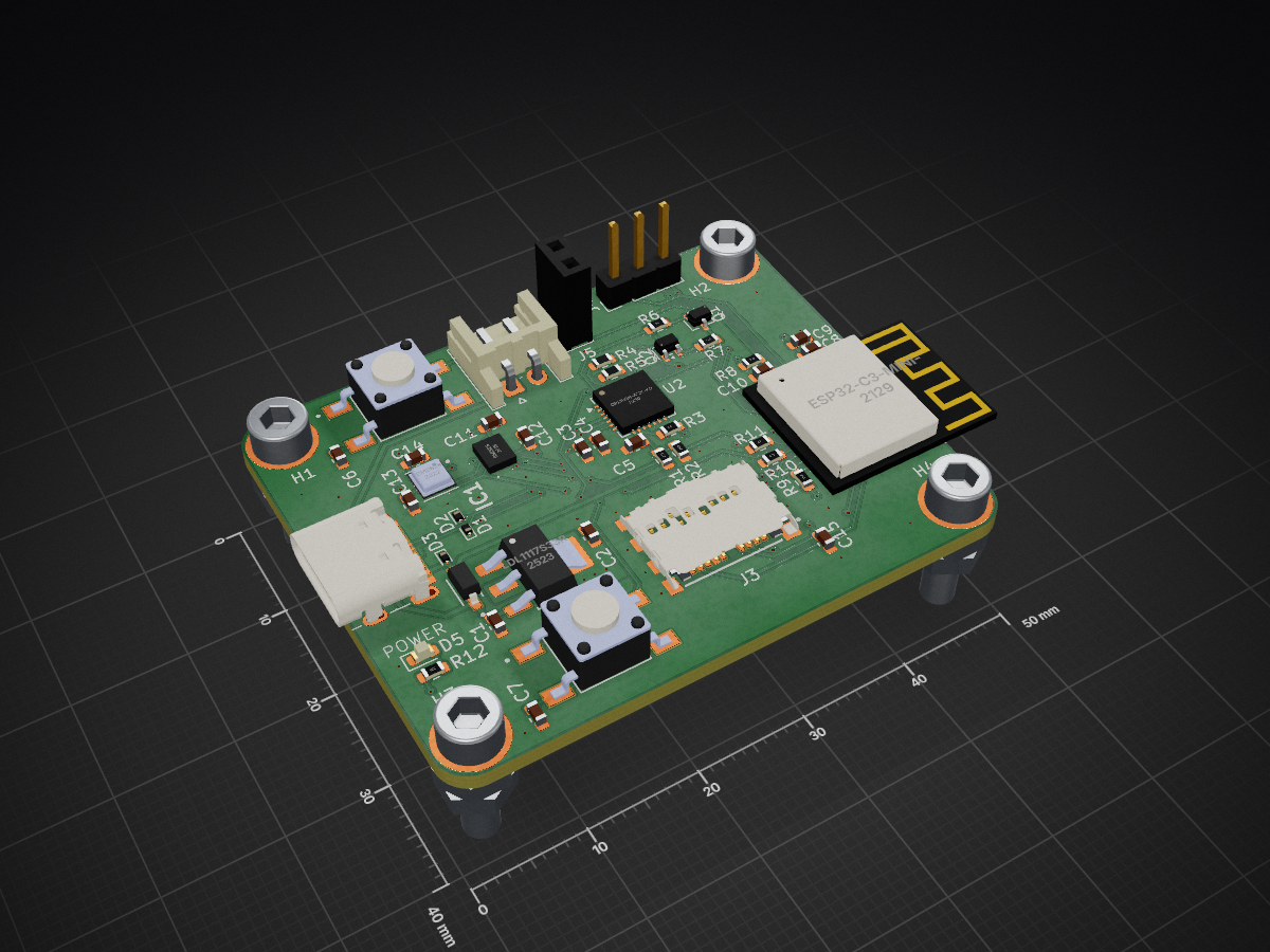
 dsimat/Node.IO-E1
Node.IO E1 is an open-source printed circuit board by dsimat, from the dsimat/Node.IO-E1 repository on GitHub. It is a 4-layer board of 50 × 40 mm with 50 parts on 74 nets, routed with 303 tracks and 114 vias.
It is built around the BME688, CP2102N-A02-GQFN28R and MEM2085-00-115-00-A, with the BMI323, ESP32-C3-MINI-1-N4X and LDL1117S33R among its other parts. Its parts include 15 capacitors, 12 resistors, 5 ICs, 5 diodes and 5 connectors. It belongs with the ESP32 and RISC-V boards of this library.


A KiCad example project, based on the PCB Mentor Workshop. The board is a complete IOT board with two sensors: a VOC sensor and an IMU.
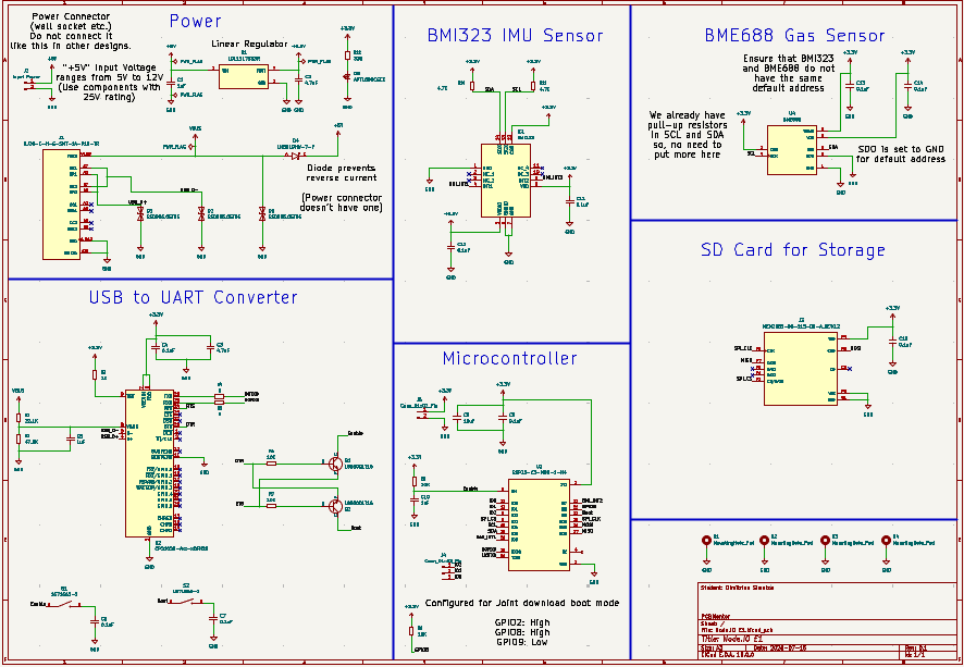
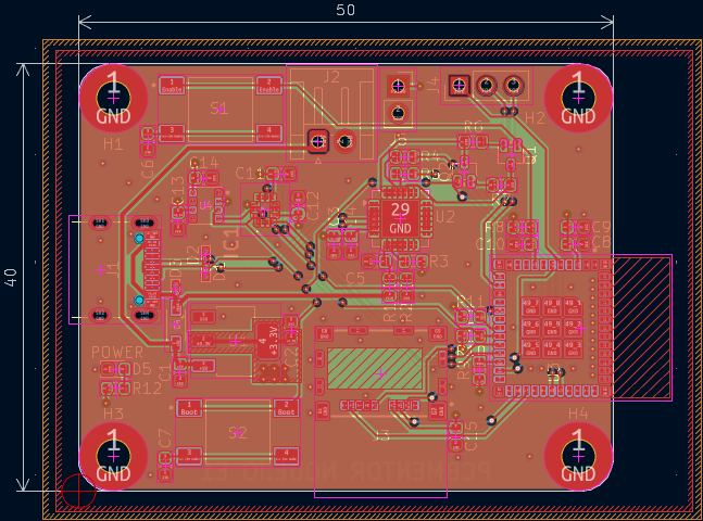
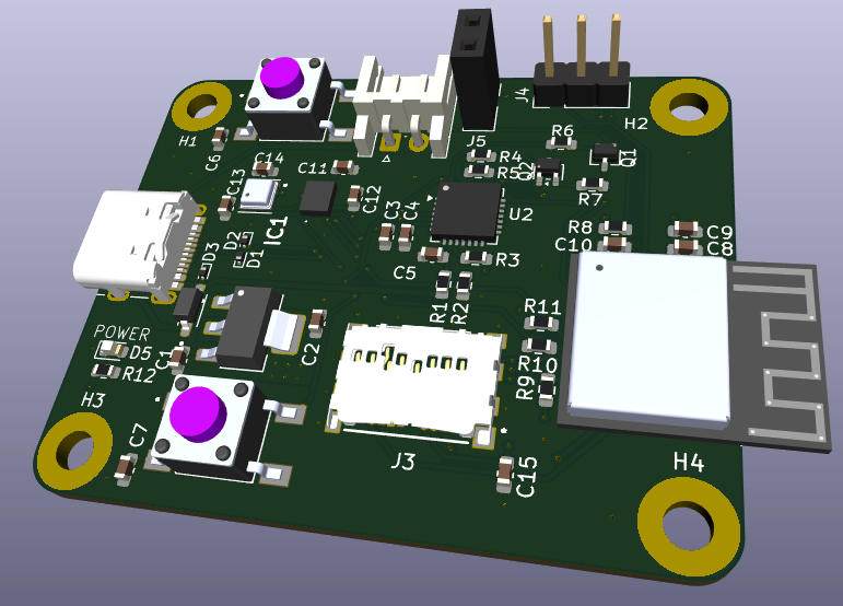
| Qty | Value | Footprint | References |
|---|---|---|---|
| 9 | 0.1uF | Capacitor_SMD:C_0603_1608Metric | C4, C6, C7, C8, C11, C12, C13, C14, C15 |
| 4 | 10K | Resistor_SMD:R_0603_1608Metric | R6, R7, R8, R9 |
| 4 | MountingHole_Pad | MountingHole:MountingHole_3mm_Pad | H1, H2, H3, H4 |
| 3 | 1uF | Capacitor_SMD:C_0603_1608Metric | C1, C5, C10 |
| 3 | ESD9B5.0ST5G | Diode_SMD:D_SOD-923 | D1, D2, D3 |
| 2 | 0 | Resistor_SMD:R_0603_1608Metric | R4, R5 |
| 2 | 1571563-2 | Node.IO:SW_1571563-2 | S1, S2 |
| 2 | 4.7K | Resistor_SMD:R_0603_1608Metric | R10, R11 |
| 2 | 4.7uF | Capacitor_SMD:C_0603_1608Metric | C2, C3 |
| 2 | L8050QLT1G | Package_TO_SOT_SMD:SOT-323_SC-70 | Q1, Q2 |
| 1 | 10uF | Capacitor_SMD:C_0603_1608Metric | C9 |
| 1 | 1K | Resistor_SMD:R_0603_1608Metric | R3 |
| 1 | 1N5819HW-7-F | Node.IO:SOD3715X145N | D4 |
| 1 | 22.1K | Resistor_SMD:R_0603_1608Metric | R1 |
| 1 | 330 | Resistor_SMD:R_0603_1608Metric | R12 |
| 1 | 47.5K | Resistor_SMD:R_0603_1608Metric | R2 |
| 1 | APT1608CGCK | LED_SMD:LED_0603_1608Metric | D5 |
| 1 | BME688 | Node.IO:BME688 | U4 |
| 1 | BMI323 | Node.IO:BMI323 | IC1 |
| 1 | CP2102N-Axx-xQFN28 | Package_DFN_QFN:QFN-28-1EP_5x5mm_P0.5mm_EP3.35x3.35mm | U2 |
| 1 | Conn_01x02_Pin | Connector_PinSocket_2.54mm:PinSocket_1x02_P2.54mm_Vertical | J5 |
| 1 | Conn_01x03_Pin | Connector_PinHeader_2.54mm:PinHeader_1x03_P2.54mm_Vertical | J4 |
| 1 | ESP32-C3-MINI-1-N4 | Node.IO:XCVR_ESP32-C3-MINI-1-N4 | U3 |
| 1 | Input Power | Connector_JST:JST_EH_S2B-EH_1x02_P2.50mm_Horizontal | J2 |
| 1 | LDL1117S33R | Node.IO:SOT230P700X180-4N | U1 |
| 1 | MEM2085-00-115-00-A_REV0.2 | Node.IO:GCT_MEM2085-00-115-00-A_REV0.2 | J3 |
| 1 | UJ20-C-H-G-SMT-1A-P16-TR | Node.IO:UJ20-C-H-G-SMT-1A-P16-TR | J1 |
It measures 50 × 40 mm and has 4 copper layers, 1.6 mm thick.
50 parts, built around the BME688, CP2102N-A02-GQFN28R, MEM2085-00-115-00-A and BMI323. The full list of its parts is on this page, with links to each part's symbol and footprint where PCBKit's library has them.
From the dsimat/Node.IO-E1 repository on GitHub, at the commit this page was made from: the board is Node.IO E1.kicad_pcb and its schematic Node.IO E1.kicad_sch. PCBKit opens the board in the browser, with nothing to install.
Its repository states no licence, so its author keeps all rights: ask dsimat before reusing the design.


Loredati-svg/TPA3116D2-Class-D-Amplifier
2×50W stereo Class-D audio amplifier based on TI TPA3116D2 – KiCad PCB design

AndreiVladescu/LibrePLC32
The goal of the project is to create a compact, hackable, and well-documented PLC platform for industrial automation experiments, prototyping, education, and open hardware development.


Hamza-Anver/OmniStimDriverBoard-PCB
This is an evaluation board to test operating principles of the OptiStim head unit.

Hamza-Anver/OmniStimEvalBoard-Hardware
This is an evaluation board to test operating principles of the OptiStim head unit.
