2 layers16.9 × 39.2 mm

 emeb/ice-dongle7
USB-C Dongle with ice40 UP5k FPGA
Ice dongle is an open-source printed circuit board by emeb, from the emeb/ice-dongle repository on GitHub, published under the MIT licence. It is a 4-layer board of 40 × 16 mm with 48 parts on 59 nets, routed with 613 tracks and 95 vias.
It is built around the ICE5LP4K-SG48I, W25Q64JWUUIQ and APS6404L-3SQR-SN, with the DRTR5V0U4S among its other parts. Its parts include 14 capacitors, 14 resistors, 7 ICs, 5 connectors and 2 diodes. It belongs with the fPGA and programmable logic boards and the FPGA and CPLD boards of this library.


USB-C Dongle with ice40 UP5k FPGA
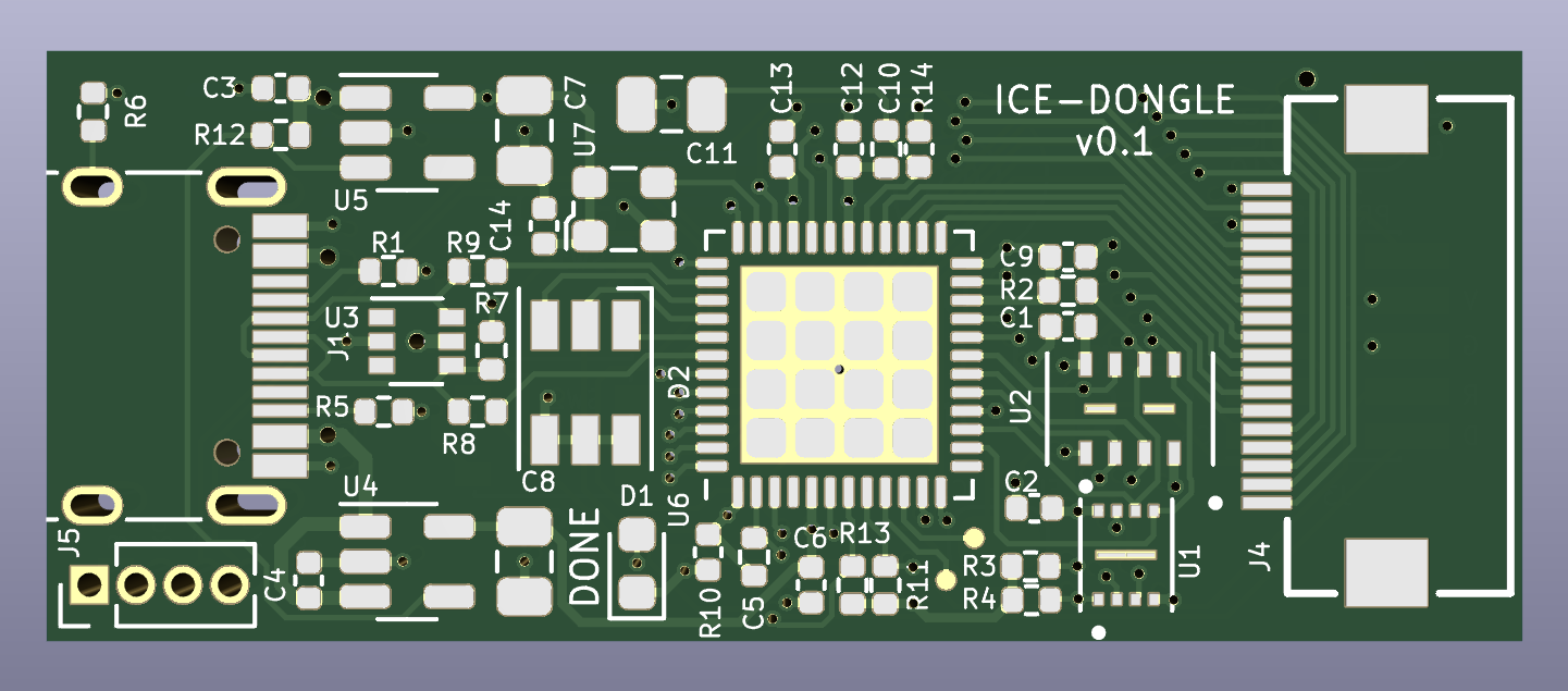
This is a small USB connected FPGA board in a "dongle" form-factor. Note that it's not a true dongle since it doesn't have a USB plug (USB-C plugs are not practical for DIY assembly at the time this was designed) - instead it has a USB-C jack and you can use an inexpensive M-M adapter to achieve dongle-like function.
For I/O it provides an 18-pin FPC connector that conforms to the Eye-SPI standard found on some Adafruit products. This standard includes 3.3V power as well as 16 GPIO for things like SPI or I2C device, most often TFT LCD displays and user interfaces.
The FPGA is directly connected to USB and is pinned-out similarly to the 1bitsquared Icebreaker Bitsy so the NO2FPGA bootloader and user designs for that ecosystem should port over with minimal changes. It includes 8MB of flash and 8MB of PSRAM, as well as an RGB LED and a user button.
Initial programming of the FPGA bitstream takes place through a 1.27mm SMD header footprint on the back of the board. The original intent was to access this temporarily via the Adafruit "Pogo Pin Probe Clip" which should have attached easily over the pads. Unfortunately the pogo pin row spacing is too narrow for the SMT header pads so I ended up soldering on a header and using a normal cable. This may be fixed in future revisions, but for now an actual header + cable is probably more reliable for long-term development.
Boards are back from OSHpark and so far things are working.
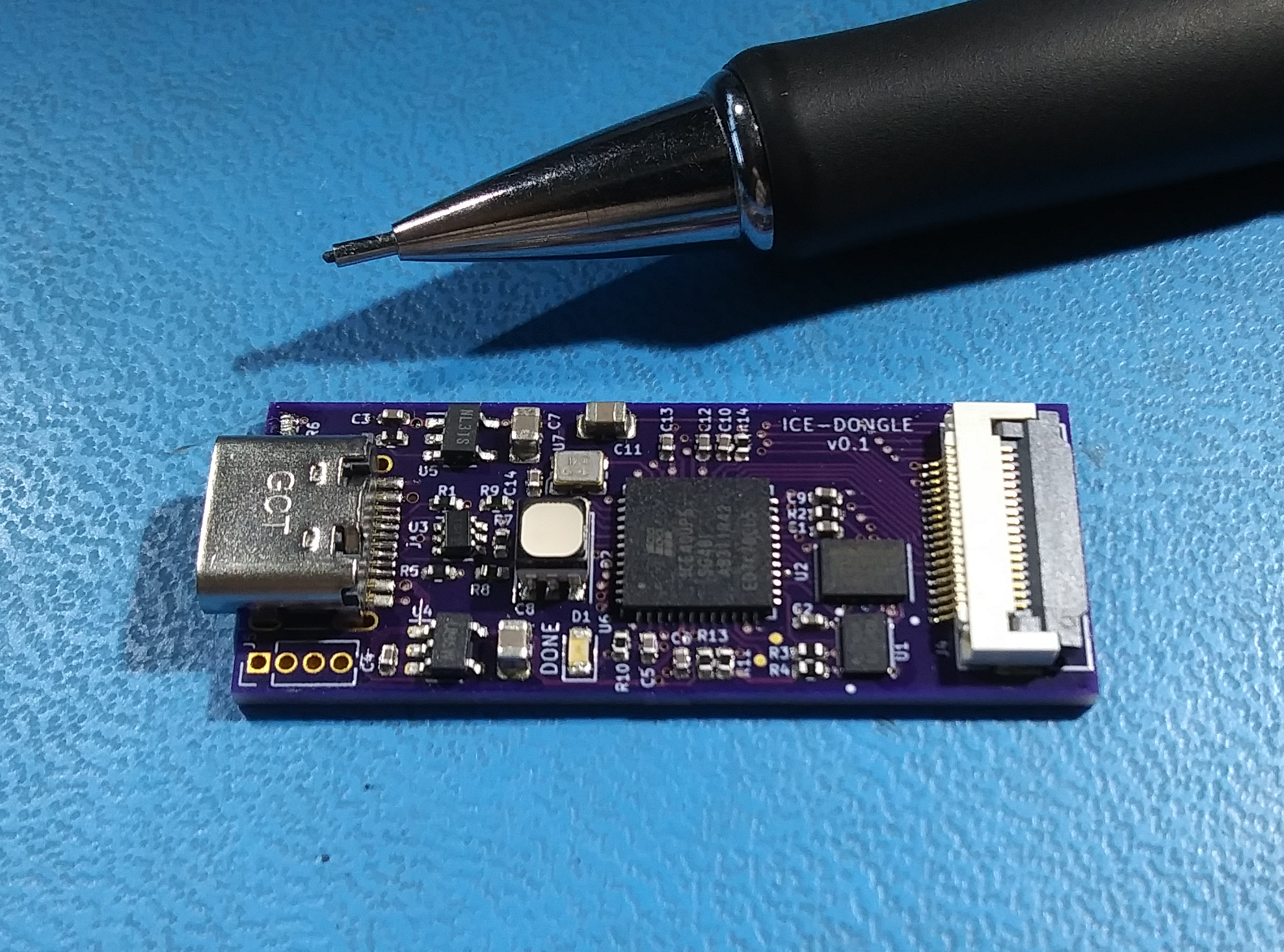
USB FS interface is fully functional with the NO2 Bootloader. I've forked it to add a custom BOARD target for ice-dongle but I'll submit a PR to the main project when things settle down a bit. For the time being here's my fork:
To build, clone that and follow the directions in the README. A few additional notes:
git submodule update --init to get all the related material
from the NO2 ecosystem.make BOARD=ice-dongle bootloaderriscv_lcd gateware project has a make dfu target that shows how to use
the bootloader.Ordered some helper boards to make interfacing easier:
find out more about them in the Hardware directory.
Corrected silkscreen errors and bumped revision to V0.1a
| Qty | Value | Footprint | References |
|---|---|---|---|
| 9 | 0.1uf | Capacitor_SMD:C_0402_1005Metric | C1, C2, C5, C6, C9, C10, C12, C13, C14 |
| 5 | 10k | Resistor_SMD:R_0402_1005Metric | R2, R3, R4, R10, R11 |
| 3 | 10uf | Capacitor_SMD:C_0805_2012Metric | C7, C8, C11 |
| 2 | 1uf | Capacitor_SMD:C_0402_1005Metric | C3, C4 |
| 2 | 22 | Resistor_SMD:R_0402_1005Metric | R8, R9 |
| 2 | 5k1 | Resistor_SMD:R_0402_1005Metric | R1, R5 |
| 2 | SW_Push | emeb_library:SW_SPST_PTS815 | SW1, SW2 |
| 2 | TestPoint | emeb_library:TestPoint_Pad_D0.5mm | TP1, TP2 |
| 1 | 1.5k | Resistor_SMD:R_0402_1005Metric | R7 |
| 1 | 100 | Resistor_SMD:R_0402_1005Metric | R14 |
| 1 | 100k | Resistor_SMD:R_0402_1005Metric | R12 |
| 1 | 12MHz | Oscillator:Oscillator_SMD_ECS_2520MV-xxx-xx-4Pin_2.5x2.0mm | U7 |
| 1 | 1M | Resistor_SMD:R_0402_1005Metric | R6 |
| 1 | 2.2k | Resistor_SMD:R_0402_1005Metric | R13 |
| 1 | APS6404L-3SQR | emeb_library:USON-8_2x3 | U1 |
| 1 | CLX6F-FKC | LED_SMD:LED_RGB_PLCC-6 | D2 |
| 1 | DRTR5V0U4S | Package_TO_SOT_SMD:SOT-363_SC-70-6 | U3 |
| 1 | FFC2B35-18-G_REVA2 | emeb_library:GCT_FFC2B35-18-G_REVA2 | J4 |
| 1 | Jumper_3_Bridged12 | Jumper:SolderJumper-3_P1.3mm_Bridged12_RoundedPad1.0x1.5mm | JP1 |
| 1 | LED Blue | LED_SMD:LED_0603_1608Metric | D1 |
| 1 | MCP1824x-OT | Package_TO_SOT_SMD:SOT-23-5 | U4 |
| 1 | NC Jumper | Jumper:SolderJumper-2_P1.3mm_Bridged_RoundedPad1.0x1.5mm | J2 |
| 1 | PROG HEADER | Connector_PinHeader_1.27mm:PinHeader_2x05_P1.27mm_Vertical_SMD | J3 |
| 1 | Qwiic | Connector_PinHeader_1.27mm:PinHeader_1x04_P1.27mm_Vertical | J5 |
| 1 | USB_C_Receptacle_USB2.0 | Connector_USB:USB_C_Receptacle_HRO_TYPE-C-31-M-12 | J1 |
| 1 | Val** | emeb_library:avatar_small | Ref** |
| 1 | W25Q64JWUUIQ | emeb_library:USON-8_4x3 | U2 |
| 1 | XC6222B331MR-G | Package_TO_SOT_SMD:SOT-23-5 | U5 |
| 1 | ice5lp4k_sg48 | Package_DFN_QFN:QFN-48-1EP_7x7mm_P0.5mm_EP5.3x5.3mm | U6 |


emeb/RP2040_Projects
A collection of random projects based on the Raspberry Pi RP2040 MCU


theta-machines/DEV-G2-NANO
The G2 Nano is powered by a record-breaking 1 GHz Arm Cortex-M7 processor, combining the performance of an application processor with real-time determinism.


Plajta/PlajTime-Hardware
Here lays the current and past HW designs of our PlajTime smartwatch. That includes all the boards and the chassis.

tsar-boomba/dap-proto-board-full
The culmination of all of my learning during the Spring '26 semester. All the way from making a simple dev board for the TAD5212 DAC, to making a RP2350 board, and now this. Everything combined on one 6-layer board.
It measures 40 × 16 mm and has 4 copper layers, 1.55 mm thick.
48 parts, built around the ICE5LP4K-SG48I, W25Q64JWUUIQ, APS6404L-3SQR-SN and DRTR5V0U4S. The full list of its parts is on this page, with links to each part's symbol and footprint where PCBKit's library has them.
From the emeb/ice-dongle repository on GitHub, at the commit this page was made from: the board is Hardware/ice-dongle/ice-dongle.kicad_pcb and its schematic Hardware/ice-dongle/ice-dongle.kicad_sch. PCBKit opens the board in the browser, with nothing to install.
Its repository publishes it under the MIT licence: you may reuse it on that licence's terms (keep the author's notice, and for a copyleft licence share your changes alike).